This article is a continuation of the series of tutorials on the LPC2148 Microcontroller (ARM7). The aim of this series is to provide easy and practical examples that anyone can understand. In the previous tutorial, we have interfaced the LCD 8-bit with LPC2148 (ARM7). In this tutorial, we are going to see how to generate LCD Custom Character (Custom Character Display Using LPC2148).
Table of Contents
Prerequisites
Before starting this tutorial we should know the below topics. If you know already, please go further.
How to generate LCD Custom Character using LPC2148
Introduction
So we know how to display alphanumeric characters in LCD. We can easily display that. Because it is already stored in the ROM memory of LCD. Before that, we should know the memories of LCD. There are three types of memory present in the LCD display.
- CG ROM
- DD RAM
- CG RAM
CG ROM (Character Generator ROM)
This memory holds the pattern for every single character of predefined LCD font. and you call the content of this memory by the placing corresponding ASCII value on the LCD port. For example, if you want to display ‘A’ you have to send the ASCII value of ‘A’ which is 0x41 to the LCD. So we cannot modify its contents which are stored already.
DD RAM (Display Data RAM)
DDRAM is the memory that holds only those characters who are currently on the screen. This means if there is a message is currently being displayed on the screen then it has to be on the DDRAM. For example, if you want to display “hello” on the screen then you have to load the pattern of h from the CG ROM to DD RAM then do the same for ‘e’ ,’l’ ,’l’ and ‘o’.
This is the address of the DDRAM memory in 16×2 LCD
| Position | 1 | 2 | 3 | 4 | ..... | 16 |
|---|---|---|---|---|---|---|
| Row1 | 0x80 | 0X81 | 0X82 | 0X83 | ...... | 0X8F |
| Row2 | 0xC0 | 0XC1 | 0XC2 | 0XC3 | ...... | 0XCF |
This memory works the same as CG ROM but as this is RAM we can modify its content at any time. So this is the place where we can store our custom character pattern. Then that pattern can be sent to display.
CG RAM (Character generator RAM)
For making custom patterns we need to write values to the CGRAM area defining which pixel to glow. These values are to be written in the CGRAM address starting from 0x40. Bit 7 is 0 and Bit 6 is 1, due to which the CGRAM address command starts from 0x40, where the address of CGRAM (Acg) starts from 0x00. CGRAM has a total of 64 Bytes. When you are using LCD as 5×8 dots in the function set then you can define a total of 8 user-defined patterns (1 Byte for each row and 8 rows for each pattern), whereas when LCD is working in 5×10 dots, you can define 4 user-defined patterns.
Custom Character Display Using LPC2148
Connection
LCD
- RS – P0.8
- RW – P0.9
- EN – P0.10
- Data Lines – P0.0 – P0.7
Source Code
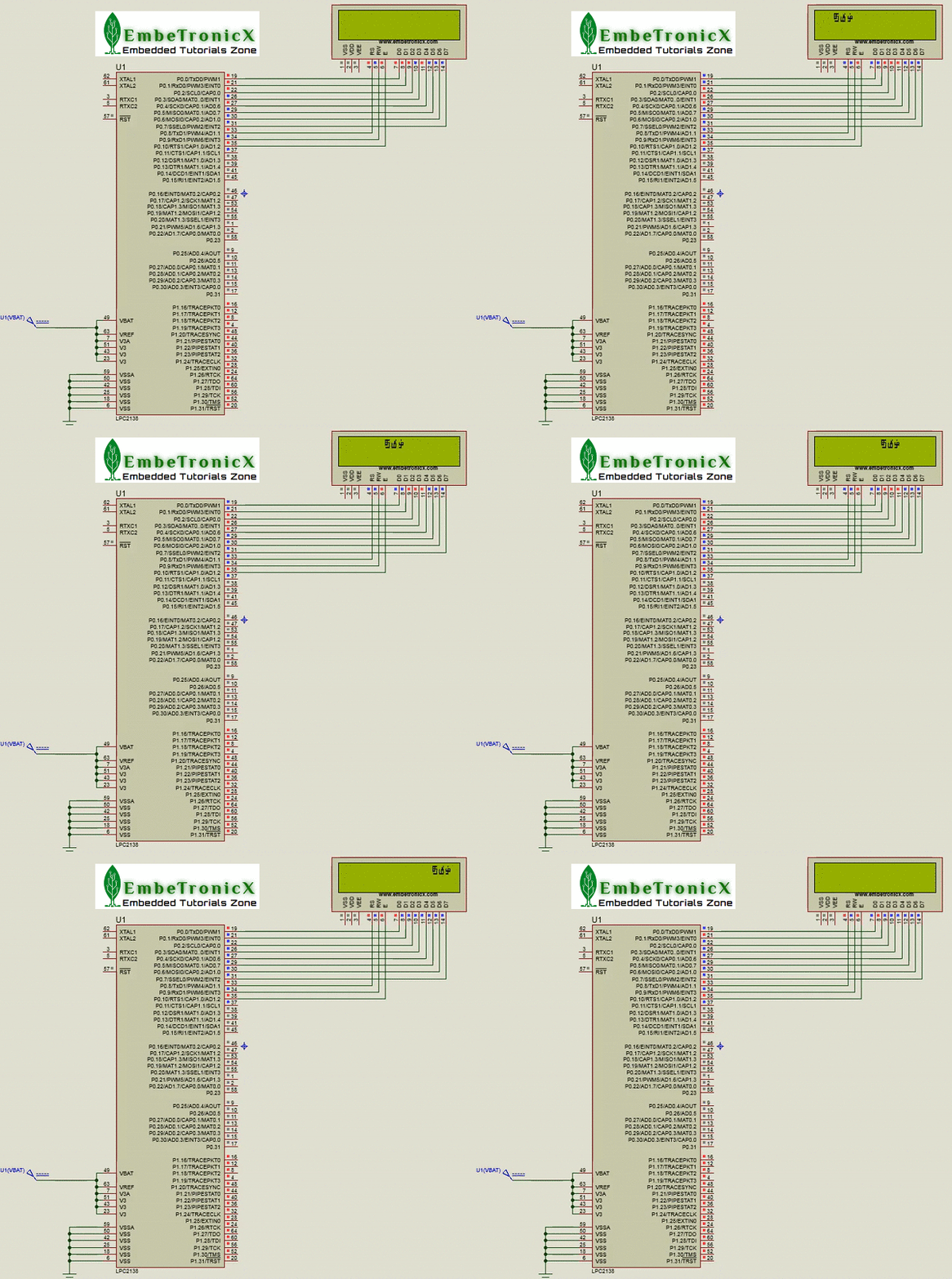
This code will print the custom character in the Tamil language. The Tamil language is not in the LCD. So that I’m going to create a few characters from Tamil. You can also try in your language or any custom character you want. See the code attached below.
#include<lpc214x.h>
#define bit(x) (1<<x)
#define delay for(i=0;i<3000;i++);

unsigned int i;

void lcd_int();
void dat(unsigned char);
void cmd(unsigned char);
void string(unsigned char *);
void store();

void main()
{
    IO0DIR|=0XFFF;
    lcd_int();
    store();              //Storing the custom characters
    while(1) {
        cmd(0x1c);        //Scroll command
        cmd(0x80);        //Location
        dat(0);
        dat(1);
        dat(2);
    }
}

void lcd_int()
{
    cmd(0x30);
    cmd(0x0c);
    cmd(0x06);
    cmd(0x01);
    cmd(0x80);
}

void cmd(unsigned char a)
{
    IO0PIN&=0x00;
    IO0PIN|=(a<<0);
    IO0CLR|=bit(8);                //rs=0
    IO0CLR|=bit(9);                //rw=0
    IO0SET|=bit(10);               //en=1
    delay;
    IO0CLR|=bit(10);               //en=0
}

void dat(unsigned char b)
{
    IO0PIN&=0x00;
    IO0PIN|=(b<<0);
    IO0SET|=bit(8);                //rs=1
    IO0CLR|=bit(9);                //rw=0
    IO0SET|=bit(10);               //en=1
    delay;
    IO0CLR|=bit(10);               //en=0
}

void string(unsigned char *p)
{
    while(*p!='\0')
    {
        dat(*p++);
    }
}

void store()
{
    cmd(64);          //First location
    dat(31);
    dat(20);
    dat(31);
    dat(21);
    dat(29);
    dat(1);
    dat(15);
    dat(0);

    cmd(72);          //Second location
    dat(1);
    dat(2);
    dat(2);
    dat(23);
    dat(21);
    dat(21);
    dat(31);
    dat(0);

    cmd(80);            //Third location
    dat(4);
    dat(0);
    dat(23);
    dat(21);
    dat(31);
    dat(4);
    dat(28);
    dat(0);
}
Output
 [ Please find the output image Here ]
In our next tutorial, we will see how to interface the LCD in 4-bit mode with LPC2148 (ARM7). If you want to use FreeRTOS on LPC2148, then please refer FreeRTOS series.
You can also read the below tutorials.

Embedded Software | Firmware | Linux Devic Deriver | RTOS
Hi, I am a tech blogger and an Embedded Engineer. I am always eager to learn and explore tech-related concepts. And also, I wanted to share my knowledge with everyone in a more straightforward way with easy practical examples. I strongly believe that learning by doing is more powerful than just learning by reading. I love to do experiments. If you want to help or support me on my journey, consider sharing my articles, or Buy me a Coffee! Thank you for reading my blog! Happy learning!


