This article is a continuation of the series of tutorials on the LPC2148 Microcontroller (ARM7). The aim of this series is to provide easy and practical examples that anyone can understand. In the previous tutorial, we have interfaced the LCD with LPC2148 (ARM7) using 4-bit mode. In this tutorial, we are going to learn DC Motor Interfacing with LPC2148. Let’s run….
Table of Contents
Suggestion to read
Introduction
When we talk about controlling the robot, the first thing that comes to mind is controlling DC motors. Interfacing DC motor to the microcontroller is a very important concept in Robotic applications. By interfacing the DC motor to the microcontroller, we can do many things like controlling the direction of the motor, controlling the speed of the motor. This article describes how to control the DC motor using the LPC2148 controller.
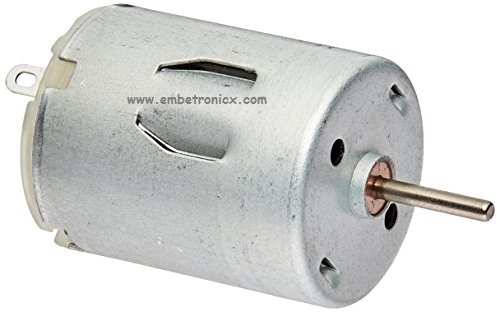
A DC motor in simple words is a device that converts electrical energy (direct current system) into mechanical energy. It is of vital importance for the industry today.
The maximum output current of the microcontroller pin is 15mA at 3.3V. But the power requirements of most DC motors are out of reach of the microcontroller and even the back emf (electromotive force) which is produced by the motor may damage the microcontroller. Hence it is not good to interface the DC motor directly to the controller. So use a motor driver circuit in between of DC motor and controller.
Here, we are using an L293D motor driver IC to drive DC motors. Using this IC, we can drive 2 DC motors at a time. For this IC motor supply is variable 4.5 to 36V and it provides a maximum current of 600mA. Just refer here for the L293d Driver’s operation.
DC Motor Interfacing with LPC2148
Circuit Diagram
- Input 1 – Port 0.0
- Input 2 – Port 0.1
- Enable 1 – Directly giving 5v

Working Algorithm
Forward
- EN Pin High (En1 = 1 or En2 = 1)
- Input 1 or Input 3 Pin High (In1 = 1 or In3=1)
- Input 2 or Input 4 Pin Low (In2 = 0 or In4 = 0)
Reverse
- EN Pin High (En1 = 1 or En2 = 1)
- Input 1 or Input 3 Pin Low (In1 = 0 or In3=0)
- Input 2 or Input 4 Pin Low (In2 = 1 or In4 = 1)
Code
In this code, the motor will rotate forward. After some time it will be OFF. Then rotates in reverse.
#include<lpc214x.h>
#define bit(x) (1<<x)
#define delay for(i=0;i<=60000;i++)

unsigned int i;

int main()
{
    IO0DIR=0xf;                     //Declaring as a output
    IO0PIN=0;                           //Clear all IO Pins in P0
    VPBDIV=0x01;                    //PCLK = 60MHz
    while(1) {
        /*Forward*/
        IO0SET=bit(0);          //IN1 = 1
        IO0CLR=bit(1);          //IN2 = 0
        delay;delay;
        /*Off*/
        IO0CLR=bit(0)|bit(1); //IN1 = IN2 = 0
        delay;delay;
        /*Reverse*/
        IO0SET=bit(1);          //IN2 = 1
        IO0CLR=bit(0);          //IN0 = 1
        delay;delay;
        /*Off*/
        IO0CLR=bit(0)|bit(1); //IN1 = IN2 = 0
        delay;delay;
    }
}
Output
 [ Please find the output image Here ]
Notes:
- The maximum current capacity of L293 is 600mA/channel. So do not use a motor that consumes more than that.
- The supply voltage range of L293 is between 4.5 and 36V DC. So you can use a motor falling in that range.
- Mostly in Robotic application, we will use DC gear Motor. So the same logic is used for that Gear motor also.
In our next tutorial, we will see how to interface the Realy with LPC2148 (ARM7). If you want to use FreeRTOS on LPC2148, then please refer FreeRTOS series.
You can also read the below tutorials.
Embedded Software | Firmware | Linux Devic Deriver | RTOS
Hi, I am a tech blogger and an Embedded Engineer. I am always eager to learn and explore tech-related concepts. And also, I wanted to share my knowledge with everyone in a more straightforward way with easy practical examples. I strongly believe that learning by doing is more powerful than just learning by reading. I love to do experiments. If you want to help or support me on my journey, consider sharing my articles, or Buy me a Coffee! Thank you for reading my blog! Happy learning!
