This article is a continuation of the series of tutorials on the LPC2148 Microcontroller (ARM7). The aim of this series is to provide easy and practical examples that anyone can understand. In the previous tutorial, we have interfaced the Relay with LPC2148 (ARM7). Now, we will see Keypad interfacing with LPC2148. Before that, I would suggest you to go through this link to know about the Keypad characteristics. Let’s start…
Table of Contents
Suggestion to read
Components Required
- 4×4 Keypad or 3×4 Keypad (Here we will discuss both codes)
- LPC2148 Microcontroller
Keypad interfacing with LPC2148
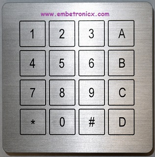
4×4 Matrix Keypad Interfacing
Circuit Diagram

Keypad
- R1 – P1.16
- R2 – P1.17
- R3 – P1.18
- R4 – P1.19
- C1 – P1.20
- C2 – P1.21
- C3 – P1.22
- C4 – P1.23
Serial
- RX – P0.0
- TX – P0.1
Code
This code might be looking complicate. Please go through this code slowly.
#include<lpc214x.h>

#define c1 (IOPIN1&1<<20)
#define c2 (IOPIN1&1<<21)
#define c3 (IOPIN1&1<<22)
#define c4 (IOPIN1&1<<23)

void ser_init(void);
void tx(unsigned char c);
unsigned char rx(void);
void tx_string(unsigned char *s);

unsigned char r_loc,c_loc;
unsigned char key[4][4]={"789/","456*","123-","C0=+"};
unsigned char keypad(void);

int main()
{
	IO1DIR=0x0f<<16;
	ser_init();
	while(1) {
		tx(keypad());
	}
}

unsigned char keypad()
{
	IO1PIN=0xf0<<16;

	while(c1 && c2 && c3 && c4);
	while(!c1 || !c2 || !c3 || !c4) {
		if(!c1 && c2 && c3 && c4)		c_loc=0;
		else if(c1 && !c2 && c3 && c4)	c_loc=1;
		else if(c1 && c2 && !c3 && c4)	c_loc=2;
		else if(c1 && c2 && c3 && !c4)	c_loc=3;

		IO1CLR = 1<<16;
		IO1SET = 0x0e<<16;
		if(!c1 || !c2 || !c3 || !c4) {
			r_loc=0;
			break;
		}

		IO1CLR = 1<<17;
		IO1SET = 0x0d<<16;
		if(!c1 || !c2 || !c3 || !c4) {
			r_loc=1;
			break;
		}

		IO1CLR = 1<<18;
		IO1SET = 0x0b<<16;
		if(!c1 || !c2 || !c3 || !c4)	{
			r_loc=2;
			break;
		}

		IO1CLR = 1<<19;
		IO1SET = 0x07<<16;
		if(!c1 || !c2 || !c3 || !c4)	{
			r_loc=3;
			break;
		}
	}
	while(!c1 || !c2 || !c3 || !c4);
	return (key[r_loc][c_loc]);
}

void ser_init()
{
	VPBDIV=0x02;					//PCLK = 30MHz
	PINSEL0=0x5;
	U0LCR=0x83;
	U0DLL=195;
	U0DLM=0;
	U0LCR=0x03;
	U0TER=(1<<7);
}

void tx(unsigned char c)
{
	U0THR=c;
	while((U0LSR&(1<<5))==0);
}

void tx_string(unsigned char *s)
{
	while(*s) {
		tx(*s++);
	}
}

unsigned char rx()
{
	while((U0LSR&(1<<0))==0);
	return U0RBR;
}
Output
Whatever we are typing in the keypad, it will send to the serial terminal.

3×4 Matrix Keypad Interfacing
Circuit Diagram
Keypad
- R1 – P1.16
- R2 – P1.17
- R3 – P1.18
- R4 – P1.19
- C1 – P1.20
- C2 – P1.21
- C3 – P1.22
Serial
- RX – P0.0
- TX – P0.1

Code
Whatever we are typing in the keypad, it will send to the serial terminal.
#include<lpc214x.h>

void ser_init(void);
void tx(unsigned char c);
unsigned char rx(void);
void tx_string(unsigned char *s);

#define c1 (IOPIN1&1<<20)
#define c2 (IOPIN1&1<<21)
#define c3 (IOPIN1&1<<22)

unsigned char r_loc,c_loc;
unsigned char key[4][3]={"123","456","789","*0#"};
unsigned char keypad(void);

int main()
{
	IO1DIR=0x0f<<16;
	ser_init();
	while(1) {
		tx(keypad());
	}
}

unsigned char keypad()
{
	IO1PIN=0xf0<<16;

	while(c1 && c2 && c3);
	while(!c1 || !c2 || !c3) {
		if(!c1 && c2 && c3)		c_loc=0;
		else if(c1 && !c2 && c3)	c_loc=1;
		else if(c1 && c2 && !c3)	c_loc=2;

		IO1CLR = 1<<16;
		IO1SET = 0x0e<<16;
		if(!c1 || !c2 || !c3) {
			r_loc=0;
			break;
		}

		IO1CLR = 1<<17;
		IO1SET = 0x0d<<16;
		if(!c1 || !c2 || !c3) {
			r_loc=1;
			break;
		}

		IO1CLR = 1<<18;
		IO1SET = 0x0b<<16;
		if(!c1 || !c2 || !c3) {
			r_loc=2;
			break;
		}

		IO1CLR = 1<<19;
		IO1SET = 0x07<<16;
		if(!c1 || !c2 || !c3) {
			r_loc=3;
			break;
		}
	}
	while(!c1 || !c2 || !c3);
	return (key[r_loc][c_loc]);
}

void ser_init()
{
	VPBDIV=0x02;					//PCLK = 30MHz
	PINSEL0=0x5;
	U0LCR=0x83;
	U0DLL=195;
	U0DLM=0;
	U0LCR=0x03;
	U0TER=(1<<7);
}

void tx(unsigned char c)
{
	U0THR=c;
	while((U0LSR&(1<<5))==0);
}

void tx_string(unsigned char *s)
{
	while(*s) {
		tx(*s++);
	}
}

unsigned char rx()
{
	while((U0LSR&(1<<0))==0);
	return U0RBR;
}
Output

In our next tutorial, we will see how to interface the GSM module with LPC2148 (ARM7). If you want to use FreeRTOS on LPC2148, then please refer FreeRTOS series.
You can also read the below tutorials.
Embedded Software | Firmware | Linux Devic Deriver | RTOS
Hi, I am a tech blogger and an Embedded Engineer. I am always eager to learn and explore tech-related concepts. And also, I wanted to share my knowledge with everyone in a more straightforward way with easy practical examples. I strongly believe that learning by doing is more powerful than just learning by reading. I love to do experiments. If you want to help or support me on my journey, consider sharing my articles, or Buy me a Coffee! Thank you for reading my blog! Happy learning!
