This article is a continuation of the series of tutorials on the LPC2148 Microcontroller (ARM7). The aim of this series is to provide easy and practical examples that anyone can understand. In the previous tutorial, we have interfaced the LDR sensor with LPC2148 (ARM7). This tutorial is all about Sound Sensor Interfacing with LPC2148.
Table of Contents
Prerequisites
Before starting this tutorial we should know the below topics. If you know already, please go further.
Components Required
- LPC2148 Development Board
- Sound Sensor
- LCD Module (To print the Sensor output)
Introduction
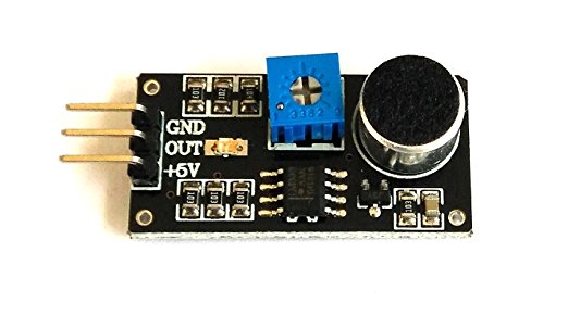
The sound detection sensor module detects whether the sound has exceeded a threshold value. Sound is detected via microphone and fed into an LM393 op-amp. The PCB of this electronic circuit has a potentiometer. The sound level setpoint is adjusted via an onboard potentiometer. When the sound level exceeds the setpoint, an LED on the module is illuminated and the output is sent low.
 Product Description

- Main chip: LM393, electret microphone
- Working voltage: DC 4 ~ 6V
- Has the signal output instructions
- Single signal output.
- Effective signal output for low level.
- Output low level and the signal light will on when there has a voice.
- Can be used for the sonic lamp, with photosensitive sensors act as sound and light alarm, also can be used in the occasion of voice control and sound detection.
- Circuit boards output switch value.
Note: This sensor only recognizes the availability of sound can not identify the size of the sound or the specific frequencies of sound.
Sound Sensor Interfacing with LPC2148
Connection
Sound Sensor
- Vcc – 5v
- GND – Ground
- Out – P1.24
LCD
- RS – P0.8
- RW – P0.9
- EN – P0.10
- Data Lines – P0.0 – P0.7

Source Code
If this sensor detects any sound, LCD will display “Sound Detected”. You can also vary the threshold level by adjusting the Potentiometer in that sensor module.
#include<lpc214x.h>
#define bit(x) (1<<x)
#define delay for(i=0;i<7000;i++);

#define SOUND (IO1PIN & (1<<24))

unsigned int i;

void lcd_int();
void dat(unsigned char);
void cmd(unsigned char);
void string(unsigned char *);

void main()
{
    IO0DIR =0XFFF;
    IO1DIR = 0x0;
    lcd_int();
    cmd(0x80);
    string("EMBETRONICX.COM ");
    while(1) {
            if(SOUND == 0) {  //When the sound detection module detects a signal, Print in the LCD
                    string("Sound Detected");
            }
            delay;delay;
            cmd(0x01);
        }
}

void lcd_int()
{
    cmd(0x38);
    cmd(0x0c);
    cmd(0x06);
    cmd(0x01);
    cmd(0x80);
}

void cmd(unsigned char a)
{
    IO0PIN&=0x00;
    IO0PIN|=(a<<0);
    IO0CLR|=bit(8);                //rs=0
    IO0CLR|=bit(9);                //rw=0
    IO0SET|=bit(10);               //en=1
    delay;
    IO0CLR|=bit(10);               //en=0
}

void dat(unsigned char b)
{
    IO0PIN&=0x00;
    IO0PIN|=(b<<0);
    IO0SET|=bit(8);                //rs=1
    IO0CLR|=bit(9);                //rw=0
    IO0SET|=bit(10);               //en=1
    delay;
    IO0CLR|=bit(10);               //en=0
}

void string(unsigned char *p)
{
    while(*p!='\0') {
        dat(*p++);
    }
}
Applications
SECURITY SYSTEM FOR HOME/OFFICE
The system can be used for home /office security purposes. When a thief or robber tries to enter the home or office, some sort of sound will be generated. It may be voice or any other sort of sound. The microphone takes the sound and sends messages instantly.
CLAPPING SWITCH
The system can be used as a clapping switch. If we add the LED with a relay or BJT, the system acts as a switch. When we clapped, the microphone takes the sound, and the comparator output goes high. As a result, BJT or relay turns on. If we connect this BJT or relay with light, fan, or any electrical/electronic instruments, the system can be operated as a clapping switch.
In our next tutorial, we will see how to interface the Touch sensor with LPC2148 (ARM7). If you want to use FreeRTOS on LPC2148, then please refer FreeRTOS series.
You can also read the below tutorials.
Embedded Software | Firmware | Linux Devic Deriver | RTOS
Hi, I am a tech blogger and an Embedded Engineer. I am always eager to learn and explore tech-related concepts. And also, I wanted to share my knowledge with everyone in a more straightforward way with easy practical examples. I strongly believe that learning by doing is more powerful than just learning by reading. I love to do experiments. If you want to help or support me on my journey, consider sharing my articles, or Buy me a Coffee! Thank you for reading my blog! Happy learning!
