This article is a continuation of the series of tutorials on the PIC16F877A Microcontroller. The aim of this series is to provide easy and practical examples that anyone can understand. In the previous tutorial, we have interfaced the GPS with PIC16F877A. In this tutorial, we are going to discuss PIR sensor interfacing with PIC16F877A. This sensor will detect motion in the room, automatic door in the elevator, automatic lighting system, and washroom amenities.
Table of Contents
Prerequisites
Before starting this tutorial we should know the below topics. If you know already, please go further.
Components Required
- PIC16F877A Development Board
- PIR Motion Sensor
- LCD Module (To print the Sensor output)
PIR Motion Sensor
Introduction
The term PIR is the short form of the Passive Infra-Red. The term “passive” indicates that the sensor does not actively take part in the process, which means, it does not emit the referred IR signals itself, rather passively detects the infrared radiations coming from the human body in the surrounding area.
The detected radiations are converted into an electrical charge, which is proportional to the detected level of the radiation. Then this charge is further improved by a built-in FET and fed to the output pin of the device which becomes applicable to an external circuit for further triggering and amplification of the alarm stages. The PIR sensor range is up to 10 meters at an angle of +15o or -15o. Most PIR modules have a 3-pin connection at the side or bottom. The pinout may vary between modules so triple-check the pinout!
Working of PIR Sensor
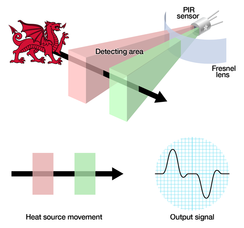
The PIR sensor itself has two slots in it, each slot is made of a special material that is sensitive to IR. The lens used here is not really doing much and so we see that the two slots can ‘see’ out past some distance (basically the sensitivity of the sensor). When the sensor is idle, both slots detect the same amount of IR, the ambient amount radiated from the room or walls or outdoors. When a warm body like a human or animal passes by, it first intercepts one-half of the PIR sensor, which causes a positive differential change between the two halves. When the warm body leaves the sensing area, the reverse happens, whereby the sensor generates a negative differential change. These change pulses are what is detected.
Adjusting PIR Sensor Settings
There are three ways to adjust the PIR sensor settings.
- Re-Triggering
- Adjust Sensitivity
- Adjust Delay
Re-Triggering
As you can see the Re-triggering section has three SMD pads. . Few PIR sensor modules come with through-hole male pin headers and it is shorted with one of the states either it is in non-re-triggering mode or re-triggering mode. We could see the two statuses High(H) and Low(L) on board. In our case, it is default connected to H. The ‘L’ mode setting behaves erratic, when we move in front of the sensor output pin goes high and low again. This is called ‘non-re-triggering mode’. In the ‘H’ mode setting when we move in infrared proximity, the output pin of the sensor will go high. This is called ‘Non-re-triggering mode’ In the ‘H’ mode setting when we move in infrared proximity the output pin of the sensor will go high. This is called ‘Re-triggering mode’. This mode of setting is a widely used setting.
Sensitivity
The PCB of this electronic circuit has a potentiometer. The potentiometer shown in the image above is provided for sensitivity adjustment. If the pot is rotated clockwise the sensitivity increases and decreases the other way around.
Delay time
The ‘delay time’ determines how much time the output pin of the sensor will keep it high when motion has been detecting. The range of the delay time of the sensor becomes few seconds to few minutes. In our case, it becomes 2 seconds to 200 seconds. Note: For the first time of testing the PIR sensor keep delay timeless.
Applications
- Intruder alarms
- Automatic ticket gates
- Entryway lighting
- Security lighting
- Hand dryers
- Automatic door
PIR Sensor Interfacing with PIC16F877A
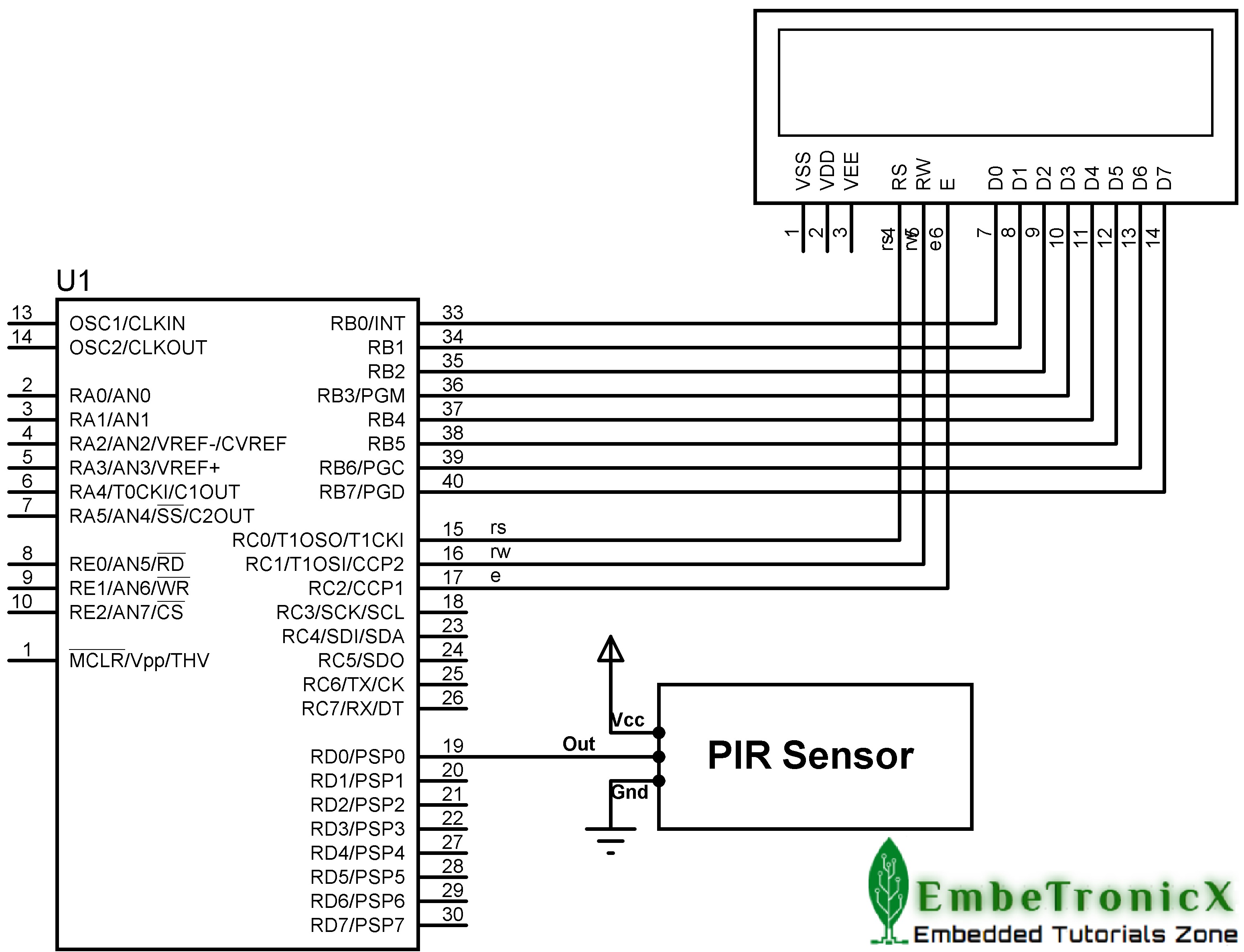
Connection
PIR Sensor
- Vcc – 5v
- GND – Ground
- Vout – RD0 (Port D.0)
LCD
- RS – RC0
- RW – RC1
- EN –RC2
- Data Lines – PORTB
Code
Whenever it detects human presence, LCD will display Intruder detected.
#include<htc.h>

__CONFIG( FOSC_HS & WDTE_OFF & PWRTE_OFF & CP_OFF & BOREN_ON & LVP_OFF & CPD_OFF & WRT_OFF & DEBUG_OFF);

#define PIR RD0                  //PIR Output is connected at PORTD.0

#define rs RC0
#define rw RC1
#define en RC2
#define delay for(i=0;i<1000;i++)

int i;

void lcd_init();
void cmd(unsigned char a);
void dat(unsigned char b);
void show(unsigned char *s);


void main()
{
    TRISB=TRISC0=TRISC1=TRISC2=0;
    TRISD=0xff;                         //Port D act as Input
    lcd_init();
    cmd(0x80);
    show("   EmbeTronicX  ");
    while(1) {
        if(PIR == 0) {
            cmd(0xc0);
            show("Intruder Detcted");
            delay;delay;
        } else {
            cmd(0xc0);
            show("                ");
        }
    }
}

void lcd_init()
{
    cmd(0x38);
    cmd(0x0c);
    cmd(0x06);
    cmd(0x80);
}

void cmd(unsigned char a)
{
    PORTB=a;
    rs=0;
    rw=0;
    en=1;
    delay;
    en=0;
}

void dat(unsigned char b)
{
    PORTB=b;
    rs=1;
    rw=0;
    en=1;
    delay;
    en=0;
}

void show(unsigned char *s)
{
    while(*s)
    {
        dat(*s++);
    }
}
You can also add a buzzer to Indicate the Human presence.
In our next tutorial, we will see how to interface the IR sensor with PIC16F877A.
You can also read the below tutorials.

Embedded Software | Firmware | Linux Devic Deriver | RTOS
Hi, I am a tech blogger and an Embedded Engineer. I am always eager to learn and explore tech-related concepts. And also, I wanted to share my knowledge with everyone in a more straightforward way with easy practical examples. I strongly believe that learning by doing is more powerful than just learning by reading. I love to do experiments. If you want to help or support me on my journey, consider sharing my articles, or Buy me a Coffee! Thank you for reading my blog! Happy learning!


