This article is a continuation of the series of tutorials on the PIC16F877A Microcontroller. The aim of this series is to provide easy and practical examples that anyone can understand. In the previous tutorial, we have interfaced the DC motor with PIC16F877A. In this tutorial, we will learn Relay interfacing with PIC16F877A. Relay is a very important component to interface the heavy appliances with the help of a microcontroller.
Table of Contents
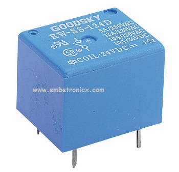
Relay
Relays are devices that allow low power circuits to switch a relatively high Current/Voltage ON/OFF. A relay circuit is typically a smaller switch or device which drives (opens/closes) an electric switch that is capable of carrying much larger current amounts.
Principle
Current flowing through the coil of the relay creates a magnetic field that attracts a lever and changes the switch contacts. The coil current can be on or off so relays have two switch positions and most have double throw (changeover) switch contacts.
Construction and working
Relays are made up of an electromagnet and a set of contacts generally based on Single Pole Double Throw (SPDT) or Double Pole Double Throw (DPDT) switching method. It has 3 pins to perform a function –
- COM = Common, always connect to NC; it is the moving part of the switch.
- NC = Normally Closed, COM is connected to this when the relay coil is off.
- NO = Normally Open, COM is connected to this when the relay coil is on.
You can easily understand the concept of Relay by looking the below image.

Prerequisites
Before Interfacing, everyone should know about the Relay Driver which is used to interface the relay to the microcontroller.
Relay Interfacing with PIC16F877A
Circuit Diagram
In this tutorial, I’m connecting One Relay in Port B.0. And the switch is connected into Port B.1.

Code
If you want to make Relay ON, Just give the High Signal (1) to that pin that is connected to ULN2803. The concept of this code is just to turn On the Relay when the button is pressed.
#include<htc.h>

#define relay RB0
#define sw RB1

void main()
{
    TRISB0=0;
    TRISB1=1;
    while(1) {
        if(sw==1){
            relay=1;
        } else {
            relay=0;
        }
    }
}
Output
 [ Please find the output image Here ]
So Programming wise it is very simple. It is like a LED program. But Hardware wise we should be careful. Because we might connect AC power supply devices here. So Be careful guys. You may connect Fan, AC Motor, Lamp, etc to relay.
In our next tutorial, we will see how to interface the Keypad with PIC16F877A.
You can also read the below tutorials.
Embedded Software | Firmware | Linux Devic Deriver | RTOS
Hi, I am a tech blogger and an Embedded Engineer. I am always eager to learn and explore tech-related concepts. And also, I wanted to share my knowledge with everyone in a more straightforward way with easy practical examples. I strongly believe that learning by doing is more powerful than just learning by reading. I love to do experiments. If you want to help or support me on my journey, consider sharing my articles, or Buy me a Coffee! Thank you for reading my blog! Happy learning!
