This article is a continuation of the series of tutorials on the PIC16F877A Microcontroller. The aim of this series is to provide easy and practical examples that anyone can understand. In the previous tutorial, we have interfaced GSM Module with PIC16F877A. In this tutorial, we are going to see RFID Interfacing with PIC16F877A. So in this tutorial, we will use EM18 RFID Reader Module. Because it will give the data via serial communication. Before interfacing please have a look at How Does RFID Works?
Table of Contents
Suggestion to read
Why EM18?
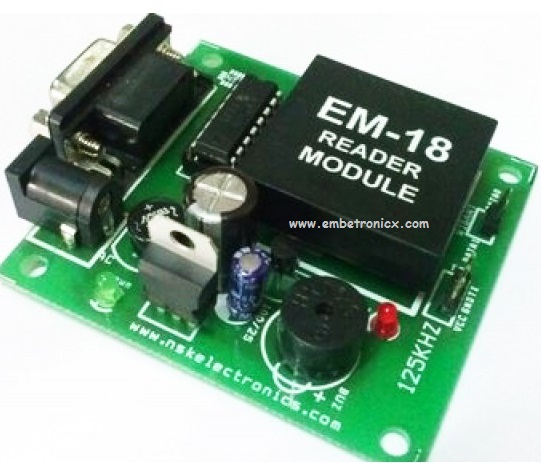
EM-18 RFID reader is one of the commonly used RFID readers to read 125KHz tags. It features low cost, low power consumption, small form factor, and easy to use. It provides both UART and Wiegand26 output formats. It can be directly interfaced with microcontrollers using UART and with PC using an RS232 converter. Just power the module, and it will read any RFID card within range.
It will output the card’s ID in a serial string, which can easily be read by any microcontroller. The spacing on the pins is 2.54 mm, which means the module will directly fit on a breadboard.
Features
- 5V supply
- 125kHz read frequency
- EM4001 64-bit RFID tag compatible
- 9600bps TTL and RS232 output
- Magnetic stripe emulation output
- 100mm read range
RFID Interfacing With PIC16F877A
Component Required
- EM18 Module
- LCD Module
- PIC16F877A Development Board
Circuit Diagram
The full circuit diagram for interfacing the RFID module to PIC16F877A is shown below. The unique ID code in the RFID card is read by the circuit and displayed on the 16×2 LCD display.
LCD:
RS – RC0
RW – RC1
EN – RC2
Data Lines – Port B
EM18 (RFID Reader):
RFID Reader TX – RC7

Programming
Programming Steps
- Initialize the LCD
- Initialize the Serial Communication (9600 BaudRate)
- Receive the 12 bytes and display them on the LCD Display
In this tutorial, I’ve displayed the 12 bytes id. But you can play with that bytes. For example, You can verify the number. If it is matching you can run the motor.
Code
In this code, I’m reading the unique id number using the polling method and printing that to LCD. You can also try using a serial interrupt.
#include<htc.h>

#define lcd_dat PORTB
#define rs RC0
#define rw RC1
#define en RC2
#define delay for(i=0;i<1000;i++)

int i;

void lcd_init();
void cmd(unsigned char a);
void dat(unsigned char b);
void show(unsigned char *s);


__CONFIG( FOSC_HS & WDTE_OFF & PWRTE_OFF & CP_OFF & BOREN_ON & LVP_OFF & CPD_OFF & WRT_OFF & DEBUG_OFF);


void ser_int();
void tx(unsigned char);
unsigned char rx();
void txstr(unsigned char *);

void main()
{
	int i;
	unsigned char id[12];
	TRISC6=TRISC7=1;
	ser_int();
	lcd_init();
	cmd(0x80);
	show("<<SHOW UR CARD>>");
	cmd(0xc0);
	for(i=0; i<12; i++) {
		id[i]=rx();
		dat(id[i]);
	}
	while(1);
}

void ser_int()
{
	TXSTA=0x20;	//BRGH=0, TXEN = 1, Asynchronous Mode, 8-bit mode
	RCSTA=0b10010000; //Serial Port enabled,8-bit reception
	SPBRG=17;			//9600 baudrate for 11.0592Mhz
	TXIF=RCIF=0;
}

void tx(unsigned char a)
{
	TXREG=a;
	while(!TXIF);
	TXIF = 0;
}

unsigned char rx()
{
	while(!RCIF);
	RCIF=0;
	return RCREG;
}

void txstr(unsigned char *s)
{
	while(*s)
	{
		tx(*s++);
	}
}

void lcd_init()
{
	TRISC0=TRISC1=TRISC2=TRISB=0;
	cmd(0x38);
	cmd(0x0c);
	cmd(0x06);
	cmd(0x80);
}

void cmd(unsigned char a)
{
	lcd_dat=a;
	rs=0;
	rw=0;
	en=1;
	delay;
	en=0;
}

void dat(unsigned char b)
{
	lcd_dat=b;
	rs=1;
	rw=0;
	en=1;
	delay;
	en=0;
}

void show(unsigned char *s)
{
	while(*s)
	{
		dat(*s++);
	}
}
You can try this code with hardware.
In our next tutorial, we will see how to interface the RTC (Real Time Clock) with PIC16F877A.
You can also read the below tutorials.
Embedded Software | Firmware | Linux Devic Deriver | RTOS
Hi, I am a tech blogger and an Embedded Engineer. I am always eager to learn and explore tech-related concepts. And also, I wanted to share my knowledge with everyone in a more straightforward way with easy practical examples. I strongly believe that learning by doing is more powerful than just learning by reading. I love to do experiments. If you want to help or support me on my journey, consider sharing my articles, or Buy me a Coffee! Thank you for reading my blog! Happy learning!
