This article is the continuation of the UDS protocol tutorial and carries the discussion on the Unified Diagnostic Services Protocol. The aim of this series is to provide easy and practical examples that anyone can understand. In the last article, we have seen the Diagnostics and Communication Management Function Group in UDS Protocol. In this tutorial, we are going to see Data Transmission in UDS Protocol.
Table of Contents
Prerequisites
Before reading this article, we are requesting you to read the below articles first.
Data Transmission in UDS Protocol
Normally, data transmission is the transfer of data from one device to another device. The data transfer will use many communication methods like I2C, SPI, etc. In those communication protocols, we will have to follow some specific procedure to read/write data from/to the memory or device. Like that, in the UDS protocol, we will have to follow some procedure to read or write data. We will get into the Data Transmission in UDS Protocol.
Data Transmission in UDS Protocol is one type of functional group that has the following services used for data transmission between the server(ECU) and client(Tester). These are some important DIDs that we use very often.
- Read Data by Identifier (0x22)
- Read Memory by Address (0x23)
- Read Scaling data by Identifier (0x24)
- Read Data by Periodic Identifier (0x2A)
- Dynamically define data Identifier (0x2C)
- Write Data by Identifier (0x2E)
- Write Memory by Address (0x3D)
Before going into detail about each service, we will learn what is Data by Identifier (DID) first.
|
|
|
Data by Identifier (DID)
Data by Identifier is a 2-byte identification code. DID is an important component for generating ECU diagnostics and troubleshooting a malfunctioning ECU. This 16-bit ID (0-65535) combines a piece of data, its length, and its description together in a DID. What each DID stands for is entirely within the scope of the computer designer.
There are many diagnostics services using DIDs. Read data byte identifier and Write data byte identifier are the most popular services using DIDs.
Some of the Example DIDs are mentioned below:
- 0xF190 – Vehicle Identification Number(VIN) – It is a 17-byte of data.
- 0xF170 – Board Part Number – It is a 4-byte data.
- 0xF18B – ECU Manufacturing Date
- 0xF19B – Calibration Date
The DID may vary depending on the OEMs. some of them may use different DIDs also.
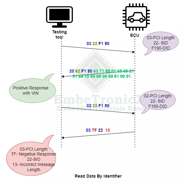
Read Data by Identifier (RDBI)
Read Data by Identifier SID is 0x22 and the Response is 0x62.
|
|
|
Read Data by Identifier services allows the tester to request the server for recorded data. With this service, the tester can retrieve one or more data from the server.
To read some sensitive data from Server using Read Data by Identifiers, the identifiers may require security access granted from the server. After getting security access from the server, then only the Client can read the data. The data identifiers list should be present with the client to read the data, else there would be a negative response sent by the server. The client can request more than one data by identifier at the same time. The ECU would combine the data for all the DIDs in one single positive response to the client.
The tester can Read the Software version of the ECU, Vehicle Identification Number, position of the vehicle, sensor data, etc., Each value is associated with a 16-bit unique DID.
Frame Format
| SID (1 byte) | Data by Identifier (2 bytes) | Padding (5 bytes) |
Example – Single DID
Let’s consider that, DID 0xF190 is used to read the Vehicle Identification Number. Then request format will be like the below.
Request Frame
|
|
|
| Service ID (SID) | Data by Identifier | Data Padding | |
| 0x22 | 0xF1 | 0x90 | 0xAAAAAAAAAA |
Positive Response Frame
| Response ID | Data by Identifier | Data Record | |
| 0x62 | 0xF1 | 0x90 | 17 bytes of Vehicle Identification Number |
Note – The above responses will be split into multiple frames as it exceeds 8 bytes (First Frame, Flow Control, and Consecutive Frames). Then it will be sent.
Negative Response Frame
| Response ID | Service Identifier | Response | |
| 0x7F | 0x22 | Negative Response Code | |
The below image will help you to understand the complete flow of the Read Data by Identifier (RDBI).
Example – Multiple DID
Okay. Now, what do we need to do if we want to send the multiple DIDs in one data? In the below example, we are going to request two data parameters that are Vehicle Identification Number(0xF190), and Board Part Number(0xF170). The data has to be formed like the below.
|
|
|
Request Frame
| Service ID (SID) | Data by Identifier – 1 | Data by Identifier – 2 | Data Padding | ||
| 0x22 | 0xF1 | 0x90 | 0xF1 | 0x70 | 0xAAAAAA |
Positive Response Frame
| Response ID | Data by Identifier – 1 | Data Record – 1 | Data by Identifier – 2 | Data Record – 2 | ||||
| 0x62 | 0xF1 | 0x90 |
17 bytes of Vehicle Identification Number
|
0xF1 | 0x70 |
4 bytes of Board Part Number |
||
Note – The above responses will be split into multiple frames as it exceeds 8 bytes (First Frame, Flow Control, and Consecutive Frames). Then it will be sent.
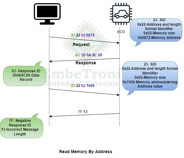
Read Memory By Address
Read memory by address SID is 0x23 and the Response is 0x63.
Read memory by address services allow the diagnostic tool to read the information from a certain region of the memory in ECU. The client requests information from the ECU by providing the starting memory address and the size of the memory to be read.
|
|
|
The starting memory address and memory size to be read is mentioned in the address and Length Format Identifier (low and high nibble) section of the request message. It is a 1- byte parameter.
A lower nibble (bit 0 to bit 3 ) indicates the memory address parameter and a Higher nibble(bit 4 to bit 7) indicates the memory size parameter.
For example, assume the address and length format identifier value is 0x24. Upper nibble 0x2 indicates memory address and lower nibble 0x4 indicates memory size. We can use a fixed address, Length Format Identifier, and unused bytes within the memory Address or memory Size parameter are padded with the value 0x00 in the higher range address locations.
While trying to read some specific memory region, ECU will ask the client whether the SID has security access to read the data or not. Once security access is granted by the ECU then only the diagnostic tool can able to read the data from the memory.
Frame Format
| SID (1 byte) | Address and Length format Identifier (1 byte) |
Memory Size (2 bytes) | Memory Address (2 bytes) |
Example
Please check the below example for reading memory by address.
|
|
|
Starting memory address – 0x6872 (16-bit address)
Memory Size – 0x02
Request Frame
| Service ID (SID) | Address and Length format Identifier | Memory Size | Memory Address | ||
| 0x23 | 0x22 | 0x02 | 0x68 | 0x72 | |
Positive Response Frame
| Response ID | Data Record | |||
| 0x63 | 0x55 | 0x0A | 0x8C | 0x00 |
Negative Response Frame
| Response ID | Response |
| 0x7F | Negative Response Code |
The below image will help you to understand the complete flow of the Read Memory By Address.
|
|
|
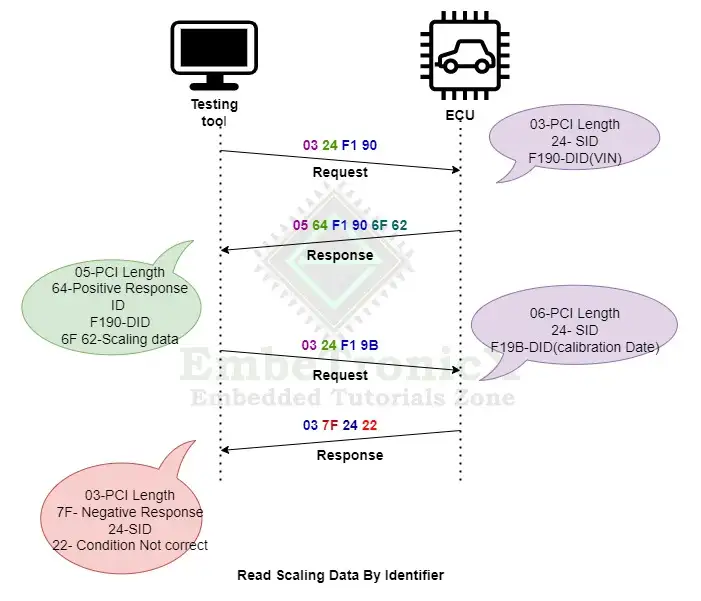
Read Scaling Data by Identifier
What is scaling data?
Scaling data means, a set of values that can be attributed to a formula can be read by the client. For example, We have to convert the data to a digital signal when we read the analog signal from the sensor. In order to change it to its equivalent digital value, we will use some constant value. Those values are called scaling data.
Read Scaling Data by Identifier SID is 0x24 and the Response is 0x64.
This service is used to read the scaling information of the record identified by a provided data identifier.
Example
Request Frame
| Service ID (SID) | Service Identifier | |
| 0x24 | 0xF1 | 0x90 |
Positive Response
|
|
|
| Response ID | Data by Identifier | Scaling Data | ||
| 0x64 | 0xF1 | 0x90 | 0x6F | 0x62 |
In the above scaling Data, 0x6F 0x62 are scaling data information.
0x6F – Indicates,
6 – Represents that the value is an ASCII value
F – Represents the total number of bytes, in this case, 15 bytes of VIN
0x62 – Indicates,
6 – Represents that the value is an ASCII value
2 – Represents the 2 leftover bytes of the VIN
Negative Response
| Response ID | Service ID (SID) | Negative Response Code |
| 0x7F | 0x24 | 0x22 |
0x22 – Condition Not Correct- The tester trying to read the Scaling information for the Calibration Date Data identifier but the scaling information is not there. The below image will help you to understand the complete flow of the Read Scaling Data by Identifier.
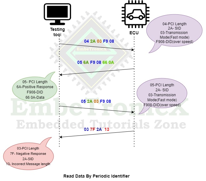
Read Data by Periodic Identifier
Read data by periodic Identifier is 0x2A and the response is 0x6A. The Read data by Periodic Identifier service allows the client to request the server to periodically transmit the response for one or more data Identifiers.
According to a request message from the server, the periodic identifier response transmission mode would be set. A new request message must be sent to the server/ECU if it has to be modified. The server will start the timer for the periodic transmission of data after transmitting a positive response with the data identifier only for the request message. To stop the service, the client must send a request message with the transmission mode set to “Stop“.
|
|
|
The ECU may limit the number of identifiers that can be supported at the same time based on the vehicle manufacturer’s design requirements. If the number of supported simultaneous identifiers is exceeded, the ECU may respond with a negative response, and none of the periodic identifiers may be scheduled. Some supporting transmission modes are below,
| Transmission Mode | Description |
|---|---|
| 0x00 | Reserved |
| 0x01 | Send at a slow rate |
| 0x02 | Send at a medium rate |
| 0x03 | Send at a fast rate |
| 0x04 | Stop sending |
| 0x05 – 0xFF | Reserved |
Example
The server wants to read the vehicle’s over speed in a periodic manner. The DID of the “read over speed of the vehicle” is 0xF908. The below image explains the Read Data by Periodic Identifier.
Dynamically define data Identifier
The Dynamically define data Identifier service ID is 0x2C and the response is 0x6C.
This service is generally recommended to be used during ECU development. This service is used when the client needs to read the response of a list of pre-defined data identifier values with another specific customized identifier. It can create a container with an identifier and add all the pre-defined identifiers to it and when this dynamically created identifier is requested, the server responds with the values of all the added pre-defined identifiers.
It is not recommended to configure one dynamically defined data identifier in another dynamically defined identifier although it can still be done. The server will maintain the records of the dynamically created data identifiers until it is cleared by the client or as per vehicle manufacturer design.
|
|
|
This service has sub-functions that have been explained in the below table.
| Sub-Function | Description |
|---|---|
| 0x00 | Reserved |
| 0x01 | Define by Identifier |
| 0x02 | Define by Address |
| 0x04 – 0x7F | Clear Dynamically Defined Data Identifier |
Request Frame
| Service ID (SID) | Sub-Function | Source ID | Dynamic Define Identifier | Size |
Positive Response Frame
| Response ID (SID+ 0x40) | Sub-function | Dynamic Define Identifier |
Write Data By Identifier (WDBI)
Write Data by Identifier SID is 0x2E and the Response is 0x6E.
Write data by identifier service allows the client (diagnostic tool) to write the information on the ECU at the memory location with the help of a Data Identifier (DID).
Request Frame
| SID (1 byte) | Data by Identifier (2 bytes) | Data parameter (n bytes) |
Positive Response Frame
| Response ID (SID+ 0X40) | Data Identifier |
Example
In the example, we are going to write the Vehicle Identification Number (0xF190) in the ECU.
Request Frame
|
|
|
| Service ID (SID) | Data by Identifier | Data parameter | ||
| 0x2E | 0xF1 | 0x90 | 17 Bytes | |
Response Frame
| Response ID | Data by Identifier | |
| 0x6E | 0xF1 | 0x90 |
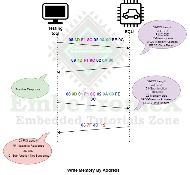
Write Memory By Address
Write Memory by Address service ID is 0x3D and Response ID is 0x7D.
Write Memory by Address service allows the diagnostic tool to write the information in ECU one or contiguous memory region. This service is used to clear the Non-volatile memory and to change the calibrating values directly in memory.
Request Frame
| Service ID (SID) | Data by Identifier | Memory Size | Memory Address | Data Information |
Positive Response Frame
| Response ID | Data by Identifier | Memory Size | Memory Address |
Example
We are going to write the ECU Serial number in a particular memory address. The DID is 0xF18C.
Request Frame
|
|
|
| Service ID (SID) | Data by Identifier | Memory Size | Memory Address | Data Parameter | |||
| 0x3D | 0xF1 | 0x8C | 0x02 | 0xA0 | 0x00 | 0xFE | 0x0C |
Positive Response Frame
| Response ID | Data by Identifier | Memory Size | Memory Address | ||
| 0x7D | 0xF1 | 0x8C | 0x02 | 0xA0 | 0x00 |
Negative Response Frame
| Response ID | Service ID (SID) | Response |
| 0x7F | 0x3D | Negative Response Code |
The below image explains the Write Data By Identifier.
|
|
|
We hope you have understood the Data Transmission in UDS Protocol. In our next article, we will see the Input Output Control in the UDS protocol.
You can also read the below tutorials.
Embedded Software Developer who is passionate about Embedded Systems.

