This article is the continuation of the UDS protocol tutorial and carries the discussion on the Unified Diagnostic Services Protocol. The aim of this series is to provide easy and practical examples that anyone can understand.
In the last article, we have seen the Introduction to the UDS protocol. In this tutorial, we are going to see function units in the UDS protocol. Especially we are going to see about Diagnostics and Communication Management and its supporting services.
First, we need to know the UDS Functional units that are available in the UDS protocol.
Table of Contents
UDS Functional Units
Diagnostics Service identifiers are categorized as below functional units,
- Diagnostics and Communication Management
- Data Transmission
- Stored Data Transmission
- Input-output control
- Remote Activation of Routine Control
- Upload/Download
In this tutorial, we will focus on Diagnostics and Communication Management.
|
|
|
Diagnostics and Communication Management
This Diagnostics and Communication Management Functional unit is to control the diagnostic and communication-related operations in the ECU.
It has the below services.
- Diagnostic Session Control -(0x10)
- ECU Reset – (0x11)
- Security Access – (0x27)
- Communication Control – (0x28)
- Authentication – (0x29)
- Tester Present – (0x3E)
- Access Timing Parameters – (0x83)
- Secured Data Transmission
- Control DTC Settings – (0x85)
- Response On Event – (0x86)
- Link Control – (0x87)
Diagnostic Session Control
The diagnostic session’s service ID is 0x10 and the Response SID is 0x50.
Diagnostic Session Control is one of the most important services used by UDS. Diagnostic Session control is used for controlling the diagnostic session of the ECU. This service is used to change the current diagnostic session to a different session.
These sessions are used to enable or disable a particular set of diagnostic functions and features in an ECU.
|
|
|
There are many services available in UDS but all the services cannot access the ECU. Some services can access only if the ECU is in the Default session and some of the other services can access the ECU in other sessions.
We can say this diagnostics session control is the gateway to access the ECU. Before doing any diagnostics operations this diagnostic service should give access to run the corresponding services. It is decided by vehicle manufacturers.
Let’s say for example In the default session we can not upgrade the software for the ECU because the Default session doesn’t have access to re-program the ECU. Only in the programming session, we have access to re-program the ECU by the authorized line engineers.
The main purpose of this diagnostic session is to give security to the ECU. It will prevent the ECU from unwanted access. And only an authorized person can access it. If every diagnostics service can access the ECU, it may get damaged by the wrong flashing of software.
So before making any diagnostic request, the Client must make sure that this service is accessible or not in the ECU current session. if not, then first send a request for session change after that desirable request shall be performed.
|
|
|
If the Server(ECU) is in a non-default session or if there is diagnostic inactivity for 5 seconds, the ECU goes back to the default session.
This has many sub-functions that have been explained in the below table.
|
Sub-function |
Description |
||
|
Default Session(0x01)
|
Example: In a garage, a person is trying to read the Diagnostic Trouble Code(DTC). |
||
|
Programming Session(0x02) |
Example: Programming session is End line engineer flashing calibration software. |
||
|
Extended Session(0x03) |
Example: This session is End of line engineers doing a dynamic vehicle test to check the security level |
||
|
Safety system Diagnostic system(0x04) |
Example: This session is checking the safety of Airbags, and tire pressure monitors. |
||
|
0x05 to 0x3F
|
Reserved |
||
|
Vehicle Manufacture Specific (0x40 to 0x5F) |
This session depends on Each OEM, If they want to implement any session based on their requirement they can use it. |
||
|
System supplier Specific (0x60 to 0X7E) |
This session is also like Vehicle Manufacture Specific only but instead of the vehicle manufacturer, if the system suppliers want to implement any session based on their specific requirement they can use it.
|
||
|
0x7F |
Reserved |
Request Frame Format:
The request frame format is given below.
|
PCI Length |
SID
|
Sub-function ID |
Response Frame Format:
There are two types of response frames. That is a Positive response and a Negative response.
Positive Response:
|
PCI Length |
SID+0x40 |
Sub-function ID
|
Negative Response:
|
PCI Length |
7F |
SID |
Negative Response Code |
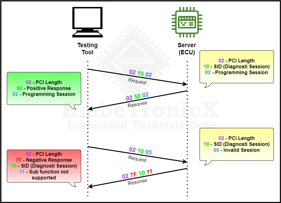
Please check the below example for the Diagnostics session transition.
|
|
|
If we want to switch from one non-default session to another non-default session, first we need to switch to the default session then we can able to switch to another non-default session.
ECU Reset
The ECU reset’s service ID is 0x11 and the Response SID is 0x51.
ECU Reset service is used to restart the particular ECU or all the ECUs in the Vehicle. The motive of this service is to recover the ECU from malfunction or hanged state or non-working condition.
During the reset of the ECU, it will not accept any request from the client and will not send any responses to the client. This service is supported in an Extended session.
|
|
|
After a successful reset, the ECU shall return to the default session.
This has many sub-functions that have been explained in the below table.
|
Sub-function |
Description |
||
|
Hard Reset (0x01)
|
|
||
|
Key off On Reset (0x02)) |
|
||
|
Soft Reset (0x03) |
For Example, will take a watchdog reset. Whenever hanging or any malfunctions are happening, this watchdog timer will reset the microcontroller and it will start from the |
||
|
Enable Rapid Power shutdown (0x04) |
|
||
|
Disable Rapid Power shutdown (0x05)
|
|
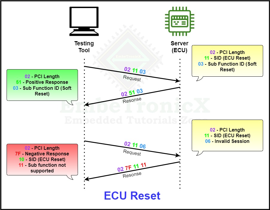
The below example explains the ECU Reset process.
Security Access
The Security Access’s service ID is 0x27 and the Response SID is 0x67.
This security access diagnostic service is used to give security access to the UDS protocol services to avoid security breaches. Some diagnostics data and services can be restricted for safety purposes.
This service will grant Read, and Write access to the particular service. Before processing any of the Service IDs(SID) operation, it’s mandatory to check the security access, to know whether, for this SID, the client has access to read or write.
|
|
|
For example, to upload and download the software, routine control and VIN(Vehicle Identification Number) DID cannot be accessed by everyone some authorized Testers can only access these SIDs.
Security access is granted based on these two,
- Seed (0x01)
- Key (0x02)
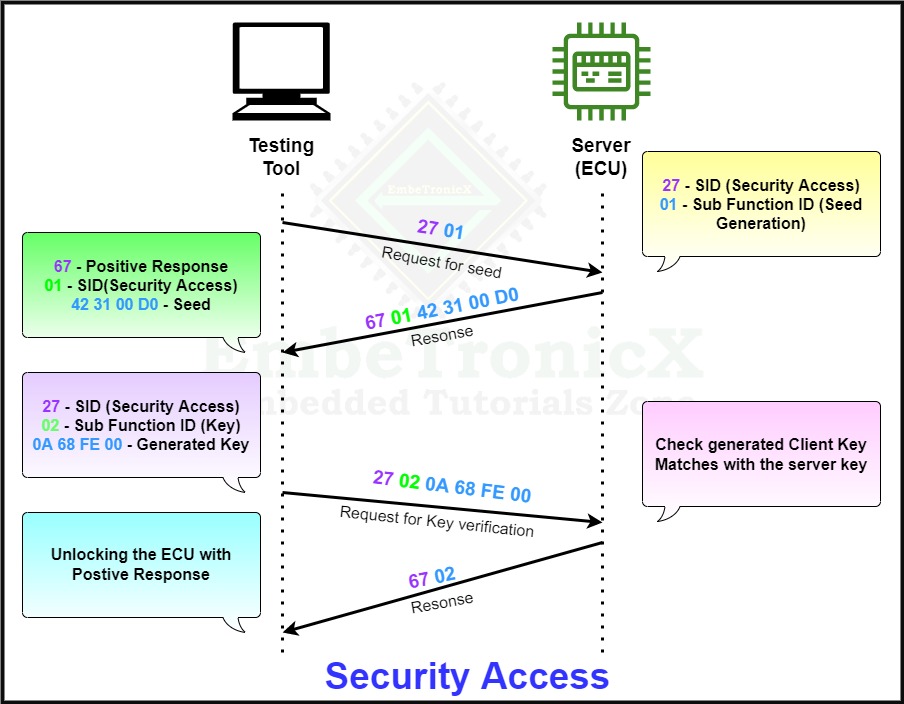
- The tester sends the request to unlock the ECU using SID 0x27 and sub-function ID 0x01. 0x01 means requesting for seed.
- The UDS server receives the request assumes conditions are correct and generates the random seed and key based on a cryptographic algorithm and the Server sends the Seed to the client with a positive response.
- With the received seed, the tester tool generates the key and sends this key to the server to unlock the ECU using SID 0x27 and sub-function ID 0x02. 0x02 means key.
- If the unlock key sent by the tester tool(client) matches with the server expecting key it will send the positive response and Unlock the ECU otherwise it will send a negative response with the specific negative response code.
The below example explains the complete process.
Communication Control
The communication control’s service ID is 0x28 and the Response SID is 0x68.
|
|
|
This communication control service is used to control the communication of the ECU server. This means this service enables or disables the transmission or reception of a message from the server(ECU) via a diagnostics line.
This service is used to control the Transmitter and receiver of the ECU. Testers can use multiple types of communication at the same time.
This service is quite useful in the context in which the communication wants to be stopped for all or a group of ECUs. For example, this can be used during a software download in order to maximize the available bandwidth.
There are 3 types of communication types available which are,
- Normal communication message (0x01)
- Network management communication message (0x02)
- Both Normal communication messages and Network management communication messages (0x03)
The sub-functions are explained in the below table.
|
|
|
|
Sub-function |
Description |
||
|
Enable Tx and Enable Rx (0x00) |
Transmission and Reception of the messages are enabled in this type. |
||
|
Enable Rx and Disable Tx (0x01)
|
Transmission of the message is disabled and the Reception of the message is enabled in this type. |
||
|
Disable Rx and Enable Tx (0x02) |
Transmission of the message is enabled and the Reception of the message is disabled in this type. |
||
|
Disable Tx and Disable Rx (0x03) |
Both Transmission and Reception of message is disabled in this type of communication.
|
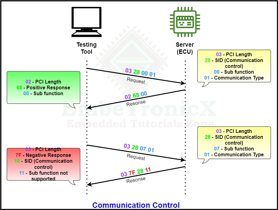
The below example explains the complete process.
Authentication
This Authentication service was added after the year 2020, and this is used to provide a standardized approach to more modern methods of authentication than are permitted by the Security Access (0x27) service, including bidirectional authentication with PKI-based Certificate Exchange.
The Authentication’s service ID is 0x29 and the Response SID is 0x69.
Tester Present
The Tester present’s service ID is 0x3E and the Response SID is 0x7E.
|
|
|
It is one of the important services in UDS protocol, We will see the purpose of this service ID.
This service is used to indicate to the server, that the client is still connected to the server. This service is used to keep the server alive in the current session except for the default session.
To keep the client in the current session ( Non-default session) tester present (0x3E) is used and the client will send this service (0x3E) periodically.
If the client is not exchanging any data with the server for more than the S3 timer value of approximately 5 seconds (this timing value is explained below in the S3 timer), the server (ECU) will get disconnected for safety purposes and automatically fall back to the Default session.
The sub-functions are explained in the below table.
|
|
|
|
Sub-Function |
|
0x00 – No sub-function value beside SuppressPosResMsgIndication (SPRMI) not supported |
|
0x80 – SuppressPosResMsgIndication (SPRMI) support (7th bit has been set – (SPRMIB)) |
What is an S3 timer?
The S3 server parameter is the server (ECU) side timing parameter implemented in each ECUs. The main function of the S3 server parameter is to auto-return into the default session from the non-default session (programming, Extended, Safety system session) after the timeout. The timeout value is based on the S3 parameter only.
The S3 timer will start when the tester requests to change to a non-default session and the S3 timer value may vary depending on OEMs but most of the OEMs are keeping the S3 value as 5 seconds.
|
|
|
Why do we need of S3 timer?
- If the client is not doing anything in the non-default session for the period, then ECU will automatically go to the default session for safety.
- Suppose the server is not going to the default session and staying in the same non-default session after the timeout. Without knowing that If we start the vehicle, ECU will not work. Because of this, accidents or other failures may happen.
SPRMIB:
Suppress Positive Response Message Indication Bit (SPRMIB) is only supported in sub-function services with sub-function bytes. This bit is used to define whether the positive response of ECU wants to expose or not to the client.
The suppressPosResMsgIndicationBit is supported via the CAN interface only, not on the K-line and ITS interface.
If the service supports suppressPosResMsgIndicationBit, then bit 7 is interpreted as suppressPosResMsgIndicationBit.
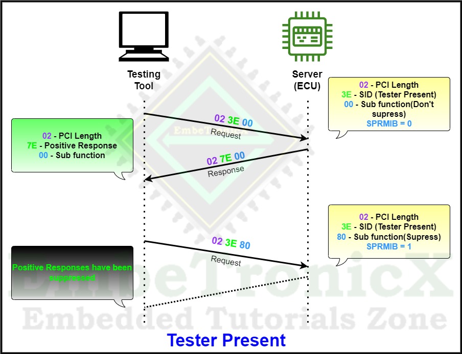
- When bit 7 is ‘1’(SPRMIB=1) then, ECU will not send the positive response to the client which means it will Suppress the positive response.
- When bit 7 is ‘0’ (SPRMIB=0) then, ECU will send the positive response to the client which means No suppression of the positive response.
- If the service is not supporting SPRMIB, then it will send the negative response (Subfunction not Supported) with suppressPosResMsgIndicationBit(SPRMIB)=1.
Note: With SPRMIB we can suppress only positive responses. Negative responses cannot be suppressed.
Here are some of the services with sub-functions that support SPRMIB.
|
|
|
-
SID
Service
0x10
Diagnostics session Control
0x11
ECU Reset
0x19
Read DTC(Diagnostic Trouble Code) information
0x27
Security Access
0x28
Communication Control
0x31
Routine Control
0x3E
Tester Present
0x83
Access Timing Parameter
0x85
Control DTC Setting
0x87
Link control
The below example explains the complete process of positive response.
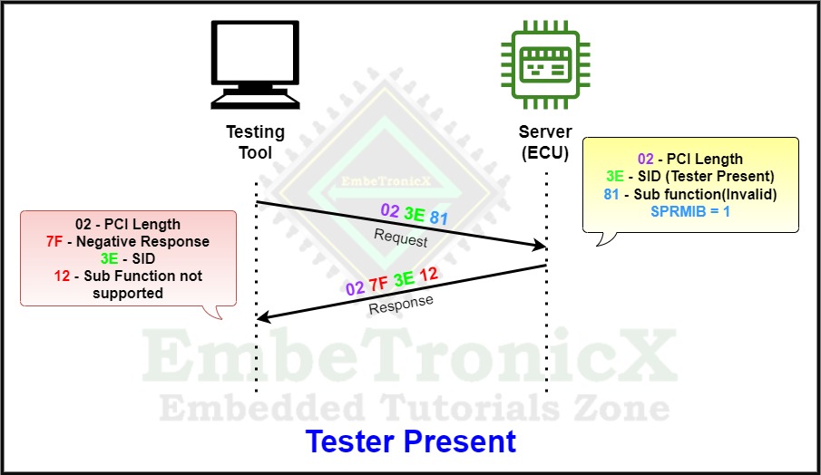
If the service is not supporting SPRMIB, then it will send the negative response (Subfunction not Supported) with suppressPosResMsgIndicationBit (SPRMIB) = 1.
|
|
|
We know the Tester present has only two sub-functions which are 0x00 and 0x80. So, 0x01 to 0x7F is not supported. If you send the not-supported sub-function, then it will send a negative response.
The below example explains the complete process of Negative response.
Access Timing Parameter
The Access timing parameter’s service ID is 0x83 and the Response SID is 0xC3.
This Access timing parameter service is used to read and write the default timing parameters of a communication link for the duration of this communication. In the communication between the controllers and the client, certain times must be observed.
|
|
|
If these are exceeded without a single message sent, it must be assumed that the connection was interrupted. By using this service the Timeout values and message separation time can be read/written.
The sub-functions are explained in the below table.
|
Sub-Function |
||
|
0x01 – Read Extended Timing Parameter Set |
||
|
0x02 – Set Timing Parameters To Default Values
|
||
|
0x03- Read Currently Active Timing Parameters |
||
|
0x04- Set Timing Parameters To Given Values |
It is recommended to use this service (0x83) in physical addressing methods because a different set of extended timing parameters is supported by the server.
Control DTC Settings
The Control DTC Settings’s service ID is 0x85 and the Response SID is 0xC5.
Generally, the Diagnostic Trouble Code(DTC) is used to indicate the failure that was caused by the ECU. In some situations, the tester may think not to detect some errors that occurred in the ECU.
|
|
|
At that time we can use this service. The control DTC Setting service is used when the client/Tester needs to stop or resume the server/ECU updating the DTC when a fault occurs.
This would be very helpful when the client knows the issue in the vehicle but is trying to find the root cause by doing some additional experiments.
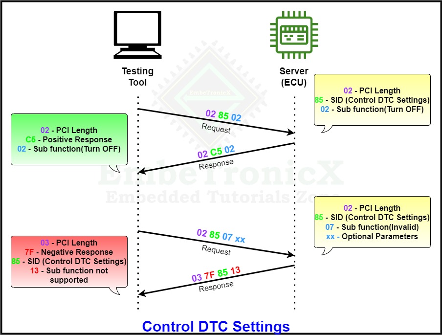
The control DTC Setting service is used to turn ON or turn OFF the detection of fault error code.
When the client requests the Server to turn OFF, the Server receives the request and temporarily turns off this feature and the server holds the current value and suspends the new value.
Later, When the client requests the server to turn ON, then the server will update with the new value.
|
|
|
If there is a Clear Diagnostic information service (0x14) requested by the user when the control DTC setting is in the OFF state, the server may still clear the DTC information.
If the client requests the service to be turned OFF when the DTC setting of the server is already in OFF mode, the server responds with a positive response and it will ignore the request.
The sub-functions are explained in the below table.
|
Sub-function |
||
|
Turn ON – 0x01
|
||
|
Turn OFF- 0x02 |
The below example explains the complete process.
Response On Event
The Response On Event’s service ID is 0x86 and the Response SID is 0xC6.
This Response On Event service requests the server to start or stop the transmission of the response on a specific event. This service automatically executes the diagnostic service when a specific event occurs without getting a request from the client.
|
|
|
The client specifies the event with optional event parameters and the service with service parameters to be executed if the event occurs. Using this service tester can Configure the ECU to send a response to the tester without a request in case any defined event occurs.
Let’s say, for example, Power interruption is an event in a vehicle. If a power interruption occurs while driving the ECU, it will not wait for the tester’s request. The ECU will send the response to the tester/client. In this case, the tester will receive a negative response.
The sub-functions are explained in the below table.
|
Sub-Function |
||
|
0x00 – Stop Response On Event
|
||
|
0x01- On DTC Status Change |
||
|
0x02 – On Timer Interrupt |
||
|
0x03 – On Change Of Data Identifier |
||
|
0x04 – Report Activated Events |
||
|
0x05 – Start Response On Event
|
||
|
0x06 – Clear Response On Event |
||
|
0x07- On Comparison Of Values |
Link Control
The Link control‘s service ID is 0x87 and the Response SID is 0xC7.
Link control can be used to change the communication parameters between the client and server to increase the baud rate. So the tester can exchange the data between the Tester and the server very quickly.
The sub-functions are explained in the below table.
|
|
|
|
Sub-Function |
|
0x01 – Verify Baud rate transition with fixed Baud rate |
|
0x02 – Verify Baud rate transition with specific Baud rate |
|
0x03 – Transition Baud rate |
Okay, We think we have covered most of the services in the Diagnostics and Communication Management Function Group. In our next tutorial, we will discuss the Data Transmission Function Group.
|
|
|
You can also read the below tutorials.
Embedded Software Developer who is passionate about Embedded Systems.

