This article is the continuation of the Series on AUTOSAR Tutorials and carries the discussion on AUTOSAR. The aim of this series is to provide easy and practical examples that anyone can understand. In the last article, we have seen the Application Layer in AUTOSAR. In this tutorial, we are going to see the Run Time Environment (RTE) Layer – AUTOSAR Tutorials Part 3.
Table of Contents
Run Time Environment Layer – RTE Layer in AUTOSAR
Run Time Environment layer acts as a middle layer between the application layer and the BSW layer in AUTOSAR Architecture. To achieve hardware-independent software RTE layer plays a main role in AUTOSAR. The RTE layer manages the inter-ECU and intra-ECU communication between application software components as well as between the application software component and the BSW module. The application layer and BSW layer communicate through RTE with the help of Virtual Functional Bus(VFB).
The virtual functional bus is the mechanism that allows these components to communicate with one another. AUTOSAR defines numerous ways for software components to interact with one another. Client-server port interface, sender-receiver, parameter interface, non-volatile data interface, Trigger Interface, and Mode Switch Interface are some of the ways software components communicate.
All the Ports and interfaces are implemented in RTE. With the help of ports and interfaces inter-ECU and intra-ECU communication is achieved in AUTOSAR. The RTE provides the communication between AUTOSAR software component (SWC) as well as AUTOSAR software components to access basic software modules including the OS and communication service. As we have seen in our previous tutorial Application Layer in AUTOSAR each SWC has multiple runnables, that can communicate with other SWC or BSW modules utilizing interfaces provided by RTE.
The RTE controls the execution of Runnable. The trigger point decides when the Runnable should run whether periodically or during a certain event like data reception with the help of RTE Events. With the help of the DaVinci configurator tool or other configurator tool, RTE will map the runnables to the OS tasks as configured during RTE configuration and execute runnables either in the same task or different task, while assigning a runnables to the corresponding task developer needs to give schedule type whether Pre-emptive type or non-preemptive type, priority, and task type.
|
|
|
RTE is different for each ECU, and Each ECU has its own customized RTE implementation which is generated during the ECU Configuration process of the AUTOSAR methodology . The ECU mapping, i.e. the information about which component will deployed on which ECU, is part of the input of this configuration process and RTE is not reusable. If the application changes, then RTE also needs to be changed. All the SWC are portable and reusable except the hardware-dependent SWC like Sensor/Actuator SWC. RTE is generated after SWC integration. Therefore, the RTE is responsible for ensuring that the system behaves as expected by ensuring that the SWCs communicate smoothly regardless of where the SWCs are deployed. RTE doesn’t support any runtime reconfiguration, i.e. every communication between SWCs and BSW modules must be configured before RTE is generated.
Inter ECU Communication
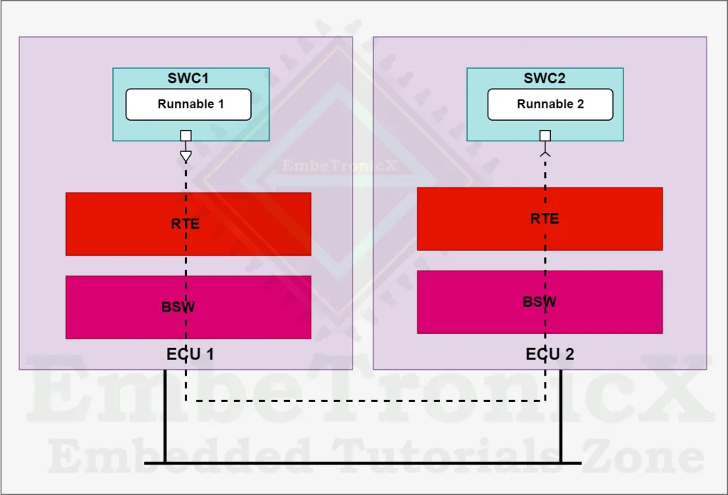
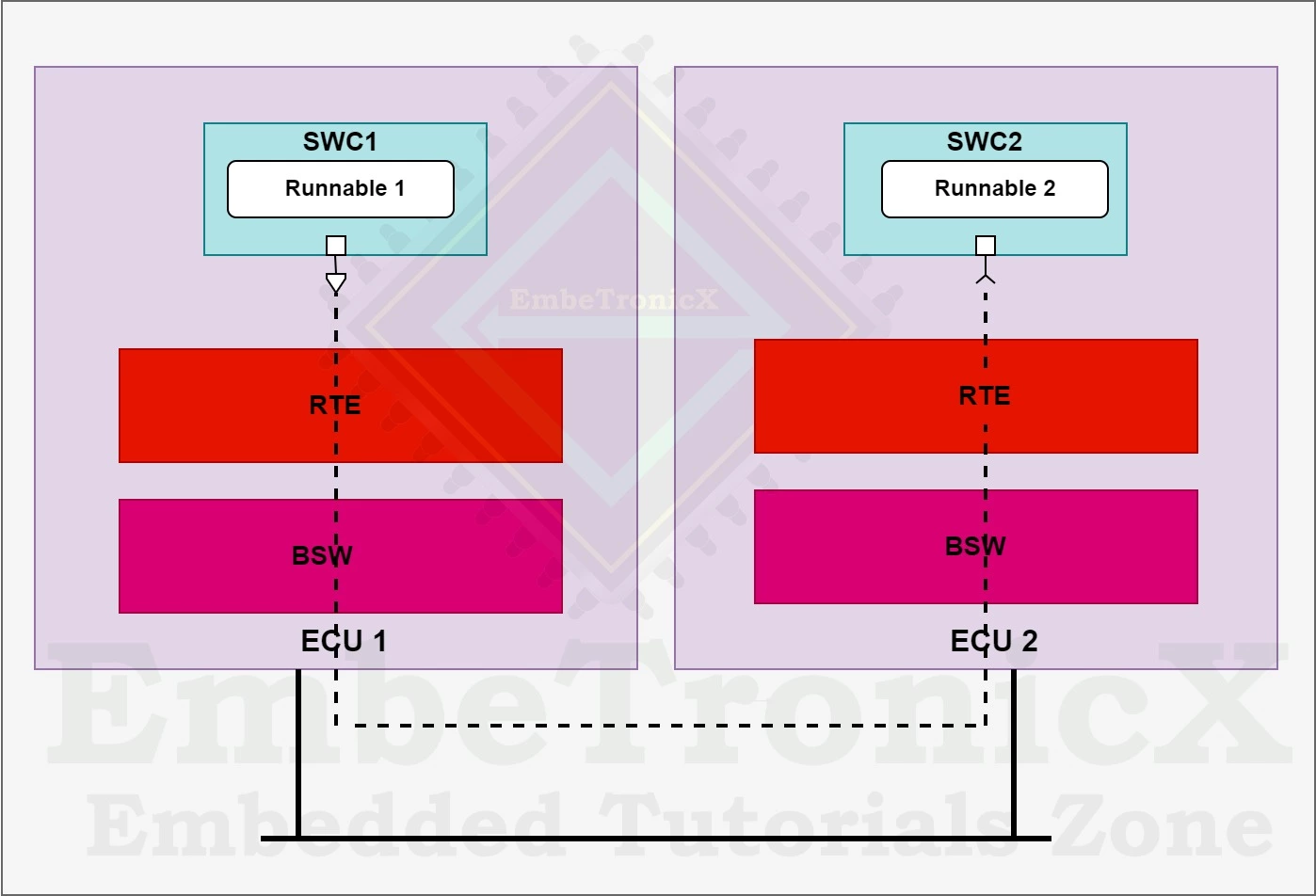
In the below example, SWC1 is mapped to ECU1 and SWC2 is mapped to ECU2, so the connection between SWC1 and SWC2 will run through a network connection between ECU1 and ECU2.
Intra ECU Communication
In the below example, SWC1 and SWC2 both are mapped to ECU1, this implies that the connectors between the first two components are handled within ECU1.
|
|
|
Virtual Functional Bus
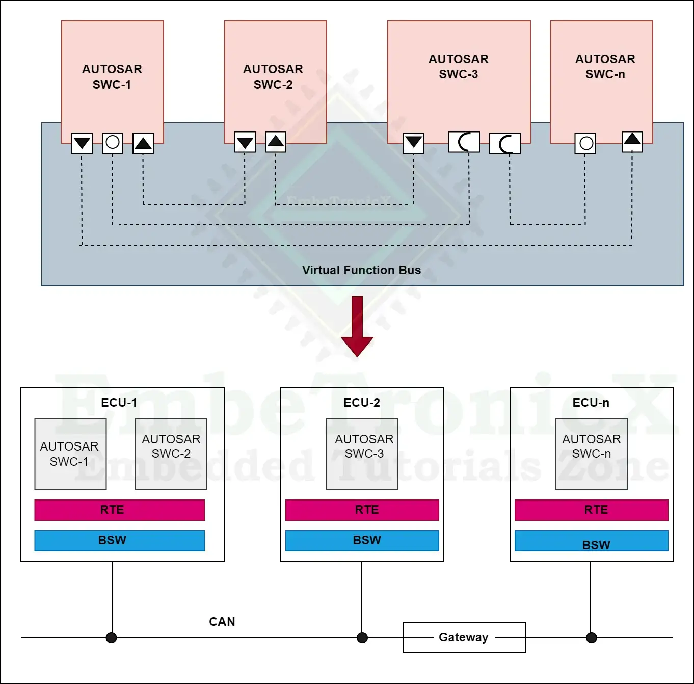
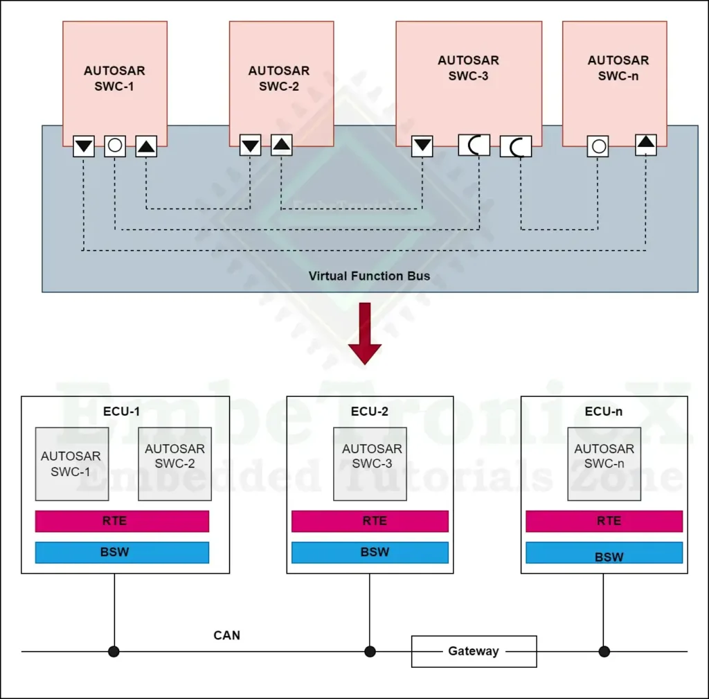
In AUTOSAR, an application is showed as a composition of interconnected components. A Virtual function bus is the communication mechanism that allows these components to interact. Components are mapped to specific system resources (ECUs). Virtual connections between components are mapped to local connections (within a single ECU) or network technology-specific communication mechanisms (e.g., CAN frames or FlexRay frames). Finally, individual ECUs can be configured within such systems. The specific interfaces between individual components and between components and the underlying software (BSW) are called run-time environments (RTEs).
The concept of the virtual functional bus allows for a strict separation between applications and infrastructure. The software components implementing the application are largely independent of the communication mechanisms through which the component interacts with other components or with hardware (such as sensors or actuators). This fulfills AUTOSAR’s goal of reloadability.
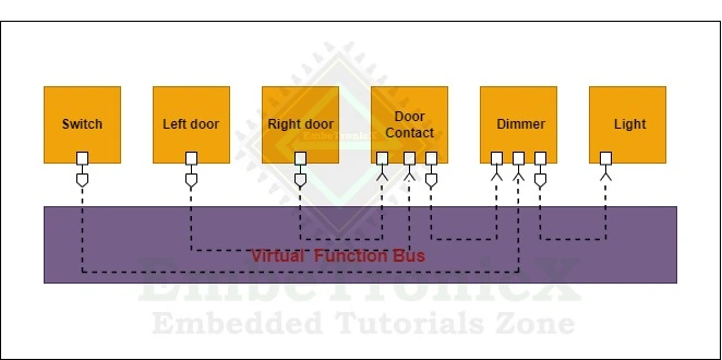
Let’s see how the RTE works in autosar architecture in the use case of light should turn on when the door is opened. ECU 1 have multiple SWC and it has two or more runnables.
When an application software component calls the READ API, the RTE reads door sensor value from the microcontroller’s I/O pins through the BSW. Sensor values are sent back to the application computer via a callback function.
In ECU1, SWC1 has runnable1 which will read the sensor value from the RTE and it may calculate how long the door is open. Runnable2 will get the value from runnable1 and compare the received value and the calibrated value. If the value exceeds the calibrated value ECU1 will send the signal to ECU2. In ECU2, runnable1 will turn on the light through the switch.
|
|
|
Responsibilities of VFB
- The Run-Time Environment (RTE) is responsible for executing the runnable in a specific sequence, setting the sequence, allocating the memory, and ensuring proper execution of the runnables.
- Two different software components can share the same memory to save memory. It is also operated by RTE.
- The OS will be running independently. The OS will trigger the RTE if it wants a task to be executed. The RTE is responsible for performing the task after receiving a trigger from OS.
- The RTE is also responsible for estimating the time required to complete a task.
- RTE also ensures that the received information is in the correct order. Byte order is maintained to ensure data reliability.
- The application software communicates with the BSW only through the RTE. However, in exceptional cases where execution speed is very critical, the BSW application software can directly access the data.
- The mode changes in the system are handled by the RTE. When a mode change occurs, it shall notify the affected software components and ensure that they can adapt their behaviour accordingly.
RTE Generation Process
RTE Contract Phase
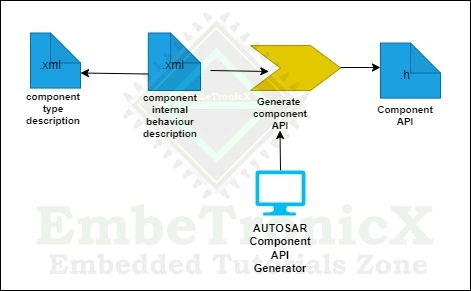
In this phase Only a few details about the component are available. At this stage, AUTOSAR interfaces are used to generate an application header file for the type of component. The application header file specifies the contract between the component and RTE.
During the contract phase, the type of application software component is defined, including ports, interfaces are defined, and connections between ports through port interfaces are defined. All these elements are defined at the VFB level, and the internal behavior description of the SW component is also defined. From this information, component API (application header file) is created.
RTE Generation Phase
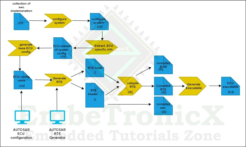
In this phase, all the necessary information about the components, deployment to the ECU, and communication between the ECU and the RTE is defined, and the data is used for the generation of the RTE. One RTE is generated per ECU per system. The RTE is set up and generated per ECU.
The two-stage development model guarantees that RTE generated application header files can be used for both source code and object code AUTOSAR components with access to all definitions generated as part of RTE generation.
The RTE Generation Phase can be split into two steps,
|
|
|
RTE Configuration editing
RTE Configuration Editor is a tool used to collect all information about the ECU to create a working RTE. Developer needs to map the event to the correspondent component. The main source of all this information is the ECU Configuration Description. Once the RTE Configuration Editor has collected all the necessary information and built its internal structure, it can start imposing requirements on the configuration of other modules such as COM and OS.
The real RTE code will only be generated by the RTE Generator after the configuration problems have been fixed. It will then be compiled and linked with the other Basic-SW modules and the SW-Components code.
RTE Generation Phase
The creation of the real RTE can be done once the ECU has been fully configured. All of the modules can be generated in parallel because all of the relationships to and from the other BSW modules were already worked out during the ECU Configuration phase.
Summary
The “Run Time Environment Layer in AUTOSAR” refers to the software layer within the AUTOSAR (AUTomotive Open System ARchitecture) standard that acts as an intermediary between the application layer and the lower-level software modules. Its main function is to manage communication between application software components and the Basic Software (BSW) layer. This includes providing APIs for inter- and intra-ECU communication, data exchange, and event handling. The RTE abstracts the complexity of the underlying system, helps in achieving modularity, and enables software components to be developed independently from hardware considerations.
You can also read the below tutorials.
|
|
|

