
This article is the first part of the Series on the UDS Protocol and carries the discussion on the Unified Diagnostic Services Protocol. The aim of this series is to provide easy and practical examples that anyone can understand. This is the UDS Protocol Introduction (Unified Diagnostic Services) – UDS Protocol Tutorial Part 1
Table of Contents
UDS Protocol Tutorial
What is the UDS Protocol?
Navigating the world of automotive embedded systems reveals a landscape bustling with diverse car manufacturers—Audi, Jaguar, BMW, Benz, and others—each employing unique architectures and software to actualize their ECUs. Gone are the days when a singular car brand should exclusively align with its own ECU.
Nowadays, collaborations extend to procuring ECUs from various manufacturers. This dynamic interplay necessitates a flexible approach to tester communication, as a uniform language cannot fit every car brand’s distinct communication needs.
Enter the solution: a standardized protocol. Termed Unified Diagnostics Services (UDS), this diagnostic communication protocol harmonizes ECU diagnosis within the global automotive electronics domain.
Experience the seamlessness of UDS as it bridges the gap between manufacturers and ushers in a new era of automotive diagnostics.
The word “Unified” means it is a common standard, not a particular company standard, so the service and functionality will be the same for all the ECU manufacturers(OEM). The word “Diagnostics” means it is a technique to identify any kind of illness(faults) of the vehicle. It also allows us to reprogram and calibrate the sensors.
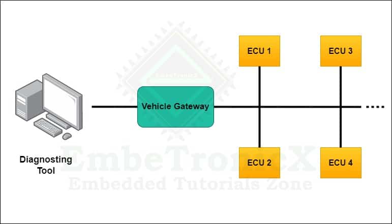
Tester to communicate with ECUs, each car has having OBD (On-Board Diagnostics) interface port. With the help of an OBD interface cable, we can connect with the car, and we can read the fault codes or reprogram or calibrate the sensors.
Why do we need diagnostics in vehicles?
In today’s modern vehicles, there are more than 100 tiny control units that handle different tasks like managing the battery, controlling the gearbox, handling braking, and even taking care of the entertainment system. But when something goes wrong, it’s like when a person gets sick.
Just as a person goes to a doctor to figure out the problem and find a solution, a vehicle needs to figure out its issue too. It does this by using something called a “fault code” or “Diagnostics Trouble Code (DTC).” This code tells us what’s wrong with the vehicle.
To help with this, there’s a special way of talking to the control units called the Unified Diagnostics Service (UDS) protocol. It’s like the vehicle asking the control unit, “Hey, what’s going on?” The control unit responds with an answer that helps us understand the problem.
We use a special tool to talk to the control units. This tool connects to the control unit and gets the fault code. It’s kind of like a translator between us and the vehicle. This communication can happen using different ways, like through CAN, LIN, or K-line methods.
So, just like people need to talk to doctors to figure out what’s wrong, vehicles use the UDS protocol and tools to talk to their control units and find out what’s going on when something isn’t right.
Difference between Communication Protocol and Diagnostic Protocol
Communication protocol means it is used to communicate between two microcontrollers or to communicate between a controller and a computer to transfer the data. In automotive electronics, we have ECUs (Electronic Control Unit). These diagnostic protocols are used to identify the faults in ECU.
Evolution of Diagnostic Protocols Standards
Before introducing UDS, there were many Diagnostic protocols like KWP2000, Diagnostics over K-Line, and ISO-15765. Automotive OEMs and suppliers have agreed to rely on Unified Diagnostic Services (UDS) as a standard protocol to ensure International compatibility.
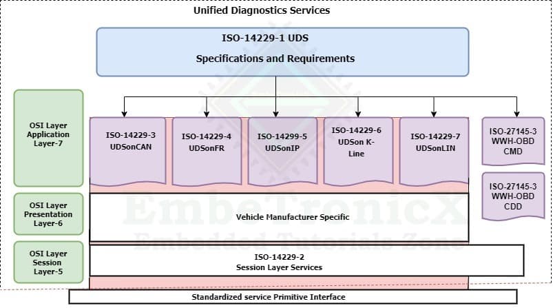
This diagnostic protocol is defined in ISO-14229 standard, This protocol is based on the Open System Interconnect (OSI) model, and it uses the fifth (Session layer) and seventh (Application layer) levels of the OSI model.
Available ISO-14229 Standards
The general UDS protocol is defined in some sub-standard of ISO-14229. Also, the standard ISO-14229 consists of the following parts,
- ISO 14229-1: Specification and requirements for UDS Protocol
- ISO 14229-2: Session layer services for UDS Protocol
- ISO 14229-3: Unified diagnostic services on CAN implementation (UDSonCAN)
- ISO 14229-4: Unified diagnostic services on FlexRay implementation (UDSonFR)
- ISO 14229-5: Unified diagnostic services on Internet Protocol implementation (UDSonIP)
- ISO 14229-6: Unified diagnostic services on K-Line implementation (UDSonK-Line)
- ISO 14229-7: Unified diagnostic services on Local Interconnect Network implementation (UDSonLIN) (Under ongoing research for implementation)
- ISO 14229-8: Unified diagnostic services on UDSon
UDS Protocol Frame Format
UDS is a Request and Response-based protocol based on client-server architecture, and it has having unique service ID(SID). SID is the size of one byte, and it ranges from 0x00 to 0x3E.
Basically, there are 4 types of frame formats,
- Request frame with sub-function ID
- Request frame without sub-function ID
- Positive Response Frame
- Negative Response Frame
Before going to know about frame format in detail, it’s good to know what is Service ID and Sub-function.
Service ID
It is a 1-byte identifier, it indicates the services which are defined in ISO-14229. The server (ECU) sees this identifier and does the operation based on this identifier.
For example, service ID: 0x11 -It is an ECU Reset.
Sub-function
It is a part of the service ID and it is an optional field.
Under ECU Reset service ID (0x11), there are 3 sub-function IDs are there.
- Hard Reset(0x01)
- Key-Off On Reset(
0x02) - Soft Reset(
0x03)
Request Frame Format
Request with Sub-function ID
The request frame is used to send the request to the server(ECU) from the client(Tester tool).
| Service ID (SID) | Sub-Function ID | Data Parameters |
Request Frame with Sub-Function ID
Request without Sub-function ID
| Service ID (SID) | Data Parameters |
Request Frame without Sub-Function ID
Response Frame Format
Positive Response Frame:
In UDS diagnostics, the tester acts as a client, and ECUs act as a server. When the server (ECU)receives the service request from the tester, the server checks the message. If everything is fine, then it executes the requested service and responds to the client with a positive response. If the response is positive, then the 6th bit of the SID should be 1.
For example,
Service ID – 0x31 => 0 0 1 1 0 0 0 1
For a positive response, 0 1 1 1 0 0 0 1 is equal to 0x71 (0x31 + 0x40).
In another way, we can say the positive response means SID+ 0x40, There is no logical reason for this. Simply, it is defined in International standard IS0-14229-1.
| Service ID (SID) + 0x40 | Sub-Function ID | Data Response Code |
Positive response with Sub-Function ID
| Service ID (SID) + 0x40 | Data Response Code |
Positive response with Sub-Function ID
Negative Response Frame:
In UDS diagnostics, the tester acts as a client, and ECUs act as a server. When the server (ECU) receives the service request from the tester, ECU checks the message. If the server finds something wrong, then it executes the negative response and sends the Negative response code(NRC). There are some Negative Response Codes given below.
- General Rejection –
0x10 - Sub-Function Not Supported –
0x12 - Incorrect Message Length(IML) –
0x13 - Busy Repeat Request –
0x21 - Condition not correct –
0x22 - Request sequence Error –
0x24 - Request Out Of Range(ROOR) –
0x31 - Security Access Denied –
0x33 - Invalid Key –
0x35
| 0x7F | Service ID | Negative Response Code |
Negative Response Frame
UDS Protocol Addressing Methods
To repair, read, write, or flash the new software, the tester needs to connect the testing tool to the ECU. If we want to connect the ECU to the system, we need to assign the address.
There are 2 types of addressing methods.
Physical Addressing
In physical addressing mode, If the tester knows which ECU is causing the issue, the tester can connect the testing tool directly to that particular ECU and get the fault code(DTC). To achieve this, each ECU should have its own ECU Identification Number.
So the tester connects with the ECU and sends the request and gets the response from the ECU. This method is called as Physical Addressing method.
Functional Addressing
In modern vehicles, a lot of ECUs are available based on the different OEMs. Suppose the tester knows there is a fault in the network(Bus) but he isn’t able to find the exact fault causing ECU in the network. Now, the tester needs to take all the ECUs’ fault codes (DTC) in the network.
In the vehicle, there will be a Global ECU Identifier, which will be implemented in all the CAN receivers. So the ECU can receive the request and give a response to the tester. This method is called as Functional Addressing method.
In our next tutorial, we will discuss the Function Group Diagnostics and Communication Management.
You can also read the below tutorials.
Embedded Software Developer who is passionate about Embedded Systems.
Share this:

Discover more from EmbeTronicX
Subscribe to get the latest posts sent to your email.
according to UDS, negative response always starts with 0x7F – there’s an error in this tutorial!
updated. Thanks for pointing out.