As you are an embedded engineer, have you thought anytime, about what happens when you press the reset button (Reset Sequence in ARM Cortex-M4 or boot sequence in Arm Cortex-M4)? How it is calling the main() function in your application automatically?
And also, If you are attending any interviews, the interviewer might have asked you this question. Okay, Let’s discuss the reset sequence in the microcontroller.
We keep posting STM32 Tutorials as a series. The aim of this series is to provide easy and practical examples that anyone can understand.
You can also read ESP32 Introduction and its flow, LPC2148 Keil Installation, LPC2148 FreeRTOS porting, LPC2148 Introduction, Linux device driver tutorial.
Table of Contents
Reset Sequence in ARM Cortex-M4
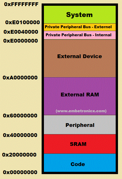
Before starting this we must know about the microcontroller memory architecture. Please find the below image to know about the Memory map of ARM Cortex-M4.
|
|
|
Here, we have a code region, where we are going to write our final binary. That memory is starting from 0x00000000 to 0x1FFFFFFF. Now we will forget about other regions. We will take only the SRAM and Code region. We know that the code region has the final output of our program (.hex or .bin or etc). SRAM will be having stack, heap, global RW variables, and Static variables, etc.
Memory layout of the program
Now we have to know how the final output of our program is stored in the code region. The below image will explain how our program is stored in the code region.  As you can see from the above image, the final output of our program will be ordered in this way by using a linker. If you want to know the memory layout of the program, you can refer to this tutorial. So, the vector table is starting from 0x00000000.
Note: By default vector table will be starting from 0x00000000.
Vector table of ARM Cortex_M4
That vector table will contain all the locations of the exception and interrupt ISR. As Cortex-M4 has below exceptions, interrupts and those things are ordered in the below image.
|
|
|
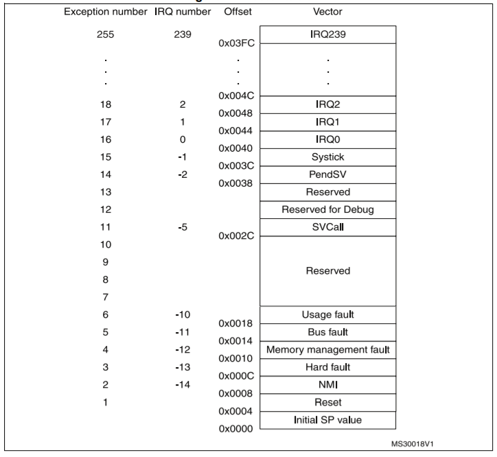 So, the
 0x00000000 address contains the initial Stack Pointer Value. Then 0x00000004 has the address of the reset handler. Once you press the reset button or power up the controller, the below things will happen.
What happens When you press the reset button in ARM Cortex-M4?
- PC (Program Counter) will be loaded with 0x00000000. So will start from the address 0x00000000.
- Since the address has an Initial Stack Pointer value, It will be fetched to the MSP (Main Stack Pointer). So, that value will be starting of the stack.
- Then PC will be loaded with the Reset handler’s address.
Note: These above 3 steps are done by the hardware (This is architecture-specific).
4. After that, the reset handler will perform the below operations.
-
-
- Initialize the system.
- Copy the Initialized global variable, static variable (.data) to SRAM.
- Copy the Un-initialized data (.bss) to SRAM and initialize it to 0.
- It Calls main().
-
This is how your main() is getting called while power-up or press the reset button. You may understand clearly if you see the execution below.
Reset Sequence in ARM Cortex-M4 – Example execution
I am using IAR IDE and STM32. Each controller has a specific startup file that has all the ISR’s addresses (vector table). In my case, I have startup_stm32l4xx.s file. I am going to run through a debugger (J-Link). Using that we will step by step.
|
|
|
I have attached some lines of the startup file.
__vector_table
        DCD     sfe(CSTACK)
        DCD     Reset_Handler             ; Reset Handler

        DCD     NMI_Handler               ; NMI Handler
        DCD     HardFault_Handler         ; Hard Fault Handler
        DCD     MemManage_Handler         ; MPU Fault Handler
        DCD     BusFault_Handler          ; Bus Fault Handler
        DCD     UsageFault_Handler        ; Usage Fault Handler
        DCD     0                         ; Reserved
        DCD     0                         ; Reserved
        DCD     0                         ; Reserved
        DCD     0                         ; Reserved
        DCD     SVC_Handler               ; SVCall Handler
        DCD     DebugMon_Handler          ; Debug Monitor Handler
        DCD     0                         ; Reserved
        DCD     PendSV_Handler            ; PendSV Handler
        DCD     SysTick_Handler           ; SysTick Handler
The above code is not a full code. I just provided some lines for your understanding. If you see the above code, the vector table’s first place contains Stack. This is the initial SP. Then after that, they have passed the Reset_Handler‘s address.
Now I am going to start debugging.
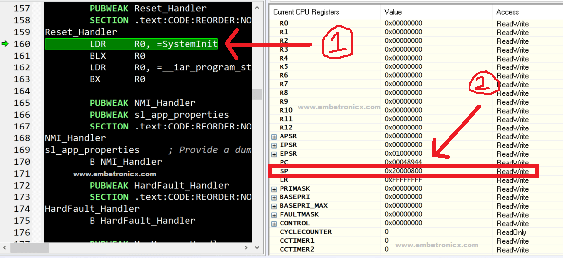
- Refer to the below image, the cursor points to
Reset_Handlerand SP also points to0x20000800. And other registers are initialized to zero. Now loading theSystemInitinto R0 register.
- Then using the BLX command, it is branching to
SystemInitfunction. There it will initialize the system. - Once it’s done with the system initialize, it will load the
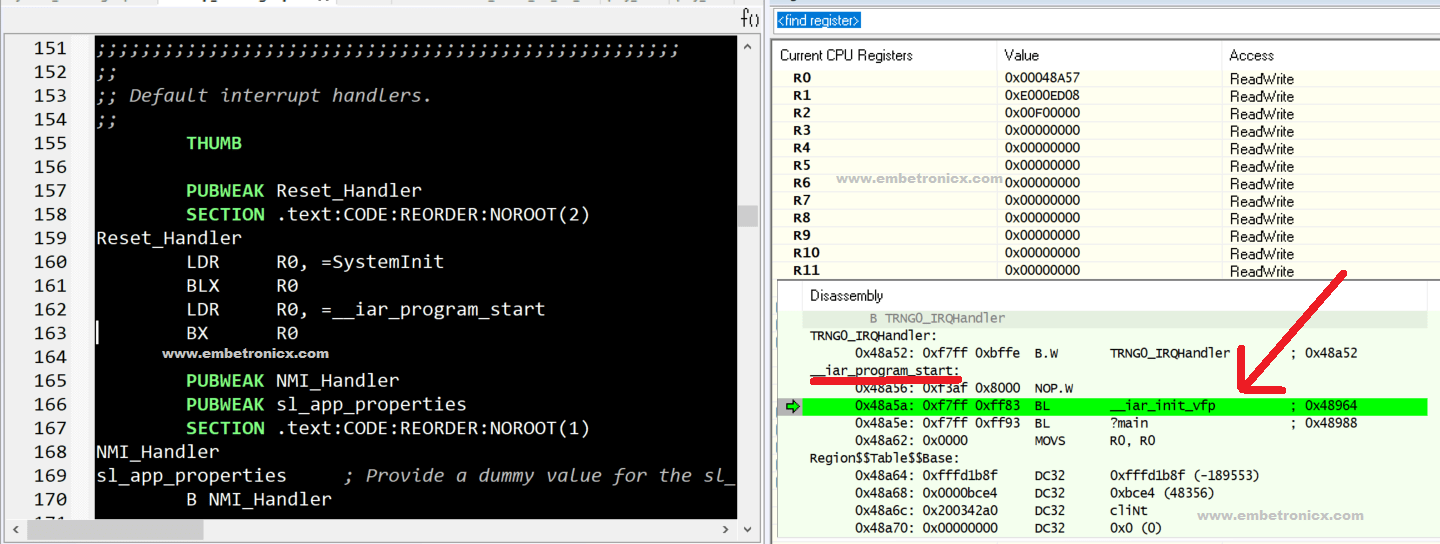
__iar_program_startto R0 register. Check out the below Image.
|
|
|
- Since we are using IAR it using
__iar_program_startfunction. This is IAR specific function. - You can not find the source of the
__iar_program_start. But you can see those kinds of stuff in the Disassembly window of IAR. - There you can see that it is going into
__iar_init_vfp,which initializes the hardware floating-point unit (FPU). Check out the below Image.
- Then there is it will jump to
?mainfunction. Check out the below Image.
- In
?main, it calls,__low_level_init. This function is intended to perform a customized initialization of your hardware that either must occur very early on or can speed up the startup process. For example, if you plan to increase the CPU clock speed, it’s better to do it sooner so that the rest of the startup code will execute faster. Check out the below Image.
- As you can see by the test of the R0 register,
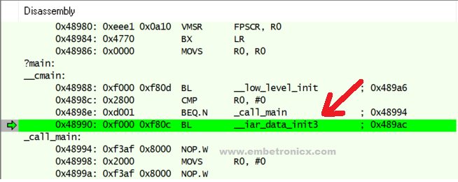
__low_level_initreturns a value that determines whether to go straight to calling main or to perform a data initialization. It returns a non-zero value, so the function__iar_data_init3is called. Check out the below Image.
__iar_data_init3will copy the data to SRAM (.data). And also copy the .bss data to SRAM and initialize it to 0 with the help of__iar_zero_init3. Check out the below Image.
|
|
|
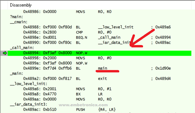
- After that, finally, it calls
_call_mainfunction. In that_call_mainfunction, we are calling the originalmain()function. Check out the below Image.
That’s all.
Summary
- When you press the reset button, it will copy the Stack pointer to MSP (Main Stack Pointer) from the location of 0x00000000.
- Then it moves to Reset_Handler.
- In the Reset_handler, it will initialize the hardware (system), then copy the initialized data (Initialized global variable and static variable) to SRAM.
- Then copy the uninitialized data to SRAM and initialize with 0.
- Finally, it calls our main function.
Note: This process is applicable when you don’t have a bootloader. If you have a bootloader, then it will execute in a different way.
What happens when you have a bootloader?
When your project has a bootloader, then you will be having two binaries. One is a Bootloader image and another one is an application. The bootloader will be placed in the 0x00000000 with its Vector Table. The application will be placed in another area of the flash memory with its vector table.
- When you press the reset button, it will start from the bootloader. So, it will copy the Stack pointer to MSP (Main Stack Pointer) from the location of 0x00000000.
- Then it moves to the bootloader’s reset handler.
- The bootloader will do some operations based on your need like check for firmware version, upgrade the firmware, etc.
- Once it has done with its operation, it will jump to the application’s vector table.
- Then it will initialize the MSP (Main Stack Pointer) again.
- Now we have to tell the controller to use the application’s vector table instead of using the bootloader’s vector table. That will be done using the Vector Table Offset Register (VTOR).
- Then it goes to the application’s reset handler. There it will copy and initialize the data segments to the RAM (Global, Static variables).
- Finally, it moves to the main function of the application.
If you want to learn about the bootloader, then we have provided a separate bootloader series for you. Please check it out.
|
|
|
Now you know how our main function is getting called? Good. Happy programming.
Please read the other STM32 Tutorials.
You can also read the below tutorials.

Embedded Software | Firmware | Linux Devic Deriver | RTOS
Hi, I am a tech blogger and an Embedded Engineer. I am always eager to learn and explore tech-related concepts. And also, I wanted to share my knowledge with everyone in a more straightforward way with easy practical examples. I strongly believe that learning by doing is more powerful than just learning by reading. I love to do experiments. If you want to help or support me on my journey, consider sharing my articles, or Buy me a Coffee! Thank you for reading my blog! Happy learning!

