
This article is the continuation of the UDS protocol tutorial and carries the discussion on the Unified Diagnostic Services Protocol. The aim of this series is to provide easy and practical examples that anyone can understand. In the last article, we have seen the Data Transmission Function Group in UDS Protocol. In this tutorial, we are going to see Input Output Control in UDS Protocol.
Table of Contents
Input Output Control in UDS Protocol
Input Output control service in UDS protocol is used in UDS to obtain an effective output. Input Output Control service ID is 0x2F and the Response is 0x6F.
This service is used by the client to substitute a value for an input signal, and internal server function, and force control to a value for an output of an electronic system. Generally, this service is used for input substitution and output control whereas routine Control is used if more complex input substitution/output control is necessary.
The request message contains the data Identifier to reference the input signal, internal server function, and force control of the output of the server. The vehicle manufacturer may require that the request message contain a control Enable Mask if the data identifier to be controlled references more than one parameter. If the vehicle manufacturer chooses to support the Enable Mask concept, then the control Enable Mask parameter is mandatory on all types of Input Output Control By Identifier requests for this service.
If input Output Control By Identifier is requested on a data Identifier that references a measured output value or feedback value, In order for the standard server control strategy to attempt to reach the desired state from the client request message, the server must substitute the proper target value within the server control strategy.
|
|
|
There is an optional byte. So, the tester can request to the server through optional bytes. There are 4 types of control parameters are used in the optional byte.
Return control to ECU
This Return control to the ECU parameter tells the server that the client has no longer access and it gets back control of the mentioned signal.
Reset to Default
This Reset to Default parameter tells the server to set the default value to the mentioned input and output signal and internal parameters.
Freeze current state
This Freeze current state parameter tells the server to freeze mentioned input, output signal, and internal parameters to their current value.
Short term adjustment
This Short term adjustment parameter tells the server to set its input, output signal, and internal parameters to the provided value.
|
|
|
Frame Format
Request Message Format
| Service ID (1 Byte) |
Data Identifier (2 Byte) |
Control Option Record (Input output control parameter and control state) (1 Byte) |
Positive Response Frame
| Control Status Record (1 Byte) |
Data Identifier (2 Byte) |
Response ID (1 Byte) |
Example
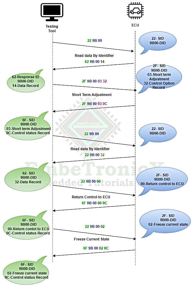
In this example, we are going to control the air inlet door position and 9B00 DID is used.
Step 1: Read the current position of the door. (values are in Hex format)
Step 2: The client has sent an input Output Control By Identifier request message with Short term adjustment. The server has sent an immediate positive response message, which includes the control State parameter “Air Inlet Door Position” with a value of 12%. The air inlet door requires a certain amount of time to move to the requested value of 50%.
Step 3: The client has sent a read Data By Identifier request message as specified above while input Output Control By Identifier is active. It will take a fixed amount of time for the server control strategy to ultimately reach the desired value. The server has finally reached the desired target value.
Step 4: The client has sent an input Output Control By Identifier request message with Return control to ECU. The server has sent an immediate positive response message.
|
|
|
Step 5: The client has sent an input Output Control By Identifier request message with Freeze current state. The server has sent an immediate positive response message with the current value.
Supported Negative Responses
- Sub function not supported – 0x12
- Incorrect message length or Invalid format – 0x13
- Conditions not correct – 0x22
- Request out of range – 0x31
- Security access denied – 0x33
In our next article, we will see the Remote Activation of Routine in the UDS protocol.
You can also read the below tutorials.
Embedded Software Developer who is passionate about Embedded Systems.
