In this post, we will discuss about Vectored Interrupt Controller and Nested Vectored Interrupt Controller (VIC and NVIC).
Please read the other STM32 Tutorials.
Table of Contents
ARM
Arm Ltd. is a British semiconductor and software design company based in Cambridge, England. Its primary business is in the design of ARM processors (CPUs).
They have started using the architecture from ARMv1 to ARMv8.6 in their processors.
It has a variety of processors that are split broadly into three main categories:
|
|
|
- Arm Cortex-A Series – Application processor cores for performance-intensive systems
- Arm Cortex-R Series – High-performance cores for real-time applications
- Arm Cortex-M Series – Microcontroller cores for a wide range of embedded applications
Cortex-A, R, M, that’s why it is called ARM? Haha…
Arm Cortex-A Series
Cortex-A processors provide a range of solutions for devices that make use of a rich operating system such as Linux or Android and are used in a wide range of applications from low-cost handsets to smartphones, tablet computers, set-top boxes, and enterprise networking equipment.
Arm Cortex-R Series
The Cortex-R processors target high-performance real-time applications such as hard disk controllers (or solid-state drive controllers), networking equipment and printers in the enterprise segment, consumer devices such as Blu-ray players and media players, and also automotive applications such as airbags, braking systems, and engine management.
Arm Cortex-M Series
The Cortex-M series is designed specifically to target the MCU market. The Cortex-M series is built on the ARMv7-M architecture (used for Cortex-M3 and Cortex-M4), and the smaller Cortex-M0+ is built on the ARMv6-M architecture. MCU vendors like TI, Silicon Labs, NXP, etc., picked up the core and started producing MCU devices.
In this post, we will be focusing on the Interrupt controller.
|
|
|
What is an Interrupt controller?
An interrupt controller is a separate peripheral like other peripherals. This is used to manage the multiple interrupts from the other peripherals or interrupt sources. Actually, the processor will have only one or a few interrupt lines. Using those few interrupt lines, we cannot control all the interrupts. So, this controller will help to manage those interrupts and tell the processor who has triggered the interrupt and which function (ISR) should the processor call.
ARM processors have been using multiple interrupt controllers in their products (licensed). Vendors also can use their own controller but mostly they use ARM’s interrupt controller. We will see some of them in this post.
Types of the interrupt controllers
- Generic Interrupt Controller (GIC)
- ARM Interrupt Controller (AITC)
- Vectored Interrupt Controller (VIC)
- Nested Vectored Interrupt Controller (NVIC)
Generic Interrupt Controller (GIC)
- (Will be added soon)
ARM Interrupt Controller (AITC)
- (Will be added soon)
Vectored Interrupt Controller (VIC)
Usually, if you take the older controllers, they will have only one ISR for multiple interrupt sources. In that ISR, we have to check the particular register and find who is interrupting the processor. So, the interrupt latency will increase if we do that in this way. To sort this issue, ARM has come up with the idea of a vector interrupt controller (VIC) where each interrupt can have separate ISR functions and those addresses will be stored in the Vector table.
The VIC provides a software interface to the interrupt system. In a system with an interrupt controller, software must determine the source that is requesting service and where its ISR is loaded. A VIC does both of these in hardware. It supplies the starting address, or vector address, of the ISR corresponding to the highest priority requesting interrupt source.
In an ARM system, two levels of interrupts are available:
|
|
|
- Fast Interrupt reQuest (FIQ) – For fast, low latency interrupt handling.
- Interrupt ReQuest (IRQ) – For more general interrupts.
Generally, you only use a single FIQ source at a time in a system to provide a true low-latency interrupt. This has the following benefits:
- You can execute the interrupt service routine directly without determining the source of the interrupt. It reduces interrupt latency.
- You can use the banked registers available for FIQ interrupts more efficiently because you do not require a context save.
The Vectored Interrupt Controller (VIC) takes 32 interrupt request inputs and programmably assigns them into 3 categories, FIQ, vectored IRQ, and non-vectored IRQ.
The following procedure shows the sequence for the vectored interrupt flow:
- When an interrupt occurs, The ARM processor branches to either the IRQ or FIQ interrupt vector.
- If the interrupt is an IRQ, read the
VICVectAddrRegister and branch to the interrupt service routine. - Stack the workspace so that you can re-enable IRQ interrupts.
- Enable the IRQ interrupts so that a higher priority can be serviced.
- Execute the Interrupt Service Routine (ISR).
- Clear the requesting interrupt in the peripheral, or write to the
VICSoftIntClearRegister if the request was generated by a software interrupt. - Disable the interrupts and restore the workspace.
- Write to the VICVectAddr Register. This clears the respective interrupt in the internal interrupt priority hardware.
- Return from the interrupt. This re-enables the interrupts.
For more information, please refer to the reference manual.
Nested Vectored Interrupt Controller (NVIC)
A nested vectored interrupt controller is used to manage the interrupts from multiple interrupt sources. NVIC is closely integrated with the processor core to achieve low-latency interrupt processing and efficient processing of late-arriving interrupts.
|
|
|
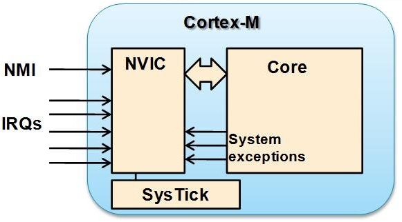
Arm cortex M controllers are using this NVIC.
NVIC Features
- External interrupts, configurable from 1 to 240.
- Bits of priority, configurable from 3 to 8.
- A dynamic reprioritization of interrupts.
- Priority grouping. This enables the selection of preempting interrupt levels and non-preempting interrupt levels.
- Support for tail-chaining and late arrival of interrupts. This enables back-to-back interrupt processing without the overhead of state saving and restoration between interrupts.
- Processor state automatically saved on interrupt entry, and restored on interrupt exit, with no instruction overhead.
- Optional Wake-up Interrupt Controller (WIC), providing ultra-low-power sleep mode support.
- Vector table can be located in either RAM or flash.
All interrupts including the core exceptions are managed by the NVIC. The NVIC maintains knowledge of the stacked, or nested, interrupts to enable tail-chaining of interrupts.
To generate the interrupt, the interrupt line should be configured and enabled. This is done by programming the two trigger registers with the desired edge detection and by enabling the interrupt request by writing a ‘1’ to the corresponding bit in the interrupt mask register. When the selected edge occurs on the external interrupt line, an interrupt request is generated. The pending bit corresponding to the interrupt line is also set. This request is reset by writing a ‘1’ in the pending register.
There are many registers present in the NVIC which I am not going to discuss here. We will see from a high-level view.
|
|
|
What happens when interrupt triggered in Cortex-M3 or M4?
The processor checks the interrupt pending register. If any one of the interrupts is in a pending state and that interrupt has been enabled already, then the processor will do the below operations.
- It finishes the current instruction.
- Then push (stacking) the 8 registers (R0, R1, R2, R3, R12, PC, LR, PSR) to the stack. (It backs up the current state. So that it can resume when it finishes the interrupt).
- The LR is loaded with the
EXC_RETURNvalue (which is one of these: 0xFFFFFFF1, 0xFFFFFFF9, 0xFFFFFFFD, 0xFFFFFFE1, 0xFFFFFFE9 or 0xFFFFFFED). - IPSR is set to the interrupt number which going to execute.
- Read the ISR address from the address register.
- PC is loaded with the ISR address and it executes the ISR.
The above steps are called context switch that occurs automatically in the hardware.
- The processor enters the ISR, it automatically moves this interrupt to the active state from the pending state.
- Once the ISR has been processed, then it will execute the BX LR.
- As LR has the special return-address
EXC_RETURN, so it will know this is returned from the ISR and start unstacking (restore or pop) the 8 registers (R0, R1, R2, R3, R12, PC, LR, PSR) from the current stack. - Then it executes the normal user program.

When will be the interrupt in the pending state?
A peripheral interrupt becomes pending for one of the following reasons:
- The NVIC detects that the interrupt signal is HIGH and the interrupt is not active.
- The NVIC detects a pulse or edge on the interrupt signal.
- Software writes to the corresponding interrupt set-pending register bit.
How long the interrupt will be in a pending state?
A pending interrupt remains pending until one of the following:
|
|
|
- The processor enters the ISR for the interrupt. This changes the state of the interrupt from pending to active. Then:
- For a level-sensitive interrupt, when the processor returns from the ISR, the NVIC samples the interrupt signal. If the signal is still asserted, the state of the interrupt changes to pending, which might cause the processor to immediately re-enter the ISR. Otherwise, the state of the interrupt changes to inactive.
- For a pulse or edge interrupt, the NVIC continues to monitor the interrupt signal, and if this is pulsed, the state of the interrupt changes to pending and active. In this case, when the processor returns from the ISR the state of the interrupt changes to pending, which might cause the processor to immediately re-enter the ISR. If the interrupt signal is not pulsed while the processor is in the ISR when the processor returns from the ISR, the state of the interrupt changes to inactive.
- Software writes to the corresponding interrupt clear-pending register bit.
- For a level-sensitive interrupt, if the interrupt signal is still asserted, the state of the interrupt does not change. Otherwise, the state of the interrupt changes to inactive.
- For a pulse interrupt, the state of the interrupt changes to:
– Inactive, if the state was pending.
– Active, if the state was active and pending.
Note: An interrupt can enter a pending state even if it is disabled. Disabling an interrupt only prevents the processor from taking that interrupt.
Why it is pushing or stacking or backing up only the 8 registers instead of all?
R0-R3 can be used for storing the input parameters/arguments of the function being called. So, we need to back up those registers as those may have the arguments of the function that is executing.
Interrupt Latency on the Cortex-M
The interrupt latency of all of the Cortex-M processors is extremely low. The exact number of cycles from the assertion of the interrupt request up to the cycle where the first instruction of the interrupt handler is ready to be expected, in a system with zero wait state memory systems:
| Processors | Cycles with zero wait state memory |
| Cortex-M0 | 16 |
| Cortex-M0+ | 15 |
| Cortex-M3 | 12 |
| Cortex-M4 | 12 |
What is nested Interrupt?
In C language, we used nested if() case, which is if() inside the another if() case. The same thing here also. Assume that the lower priority interrupt’s ISR is executing. Suddenly, a higher priority interrupt got triggered. That time, lower priority interrupt has been paused and higher priority interrupt will be executed. Once, the higher priority interrupt finishes, then the lower priority interrupts will resume. This is called a nested interrupt. The higher priority interrupt Preempts the lower priority interrupt (Preemption). Look at the below image. You will understand it in a better way.

|
|
|
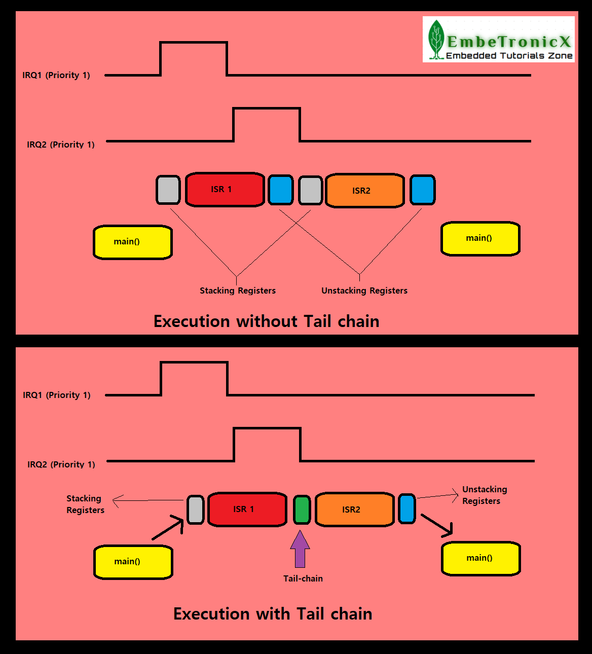
Tail chaining
This is one of the great features to reduce interrupt latency when multiple interrupts are in a pending state. Assume this scenario. IRQ1 got triggered. Then processor will stack the registers to the stack and switch to the ISR. During the execution of the ISR, another IRQ2 got triggered which is the same priority as IRQ1 or less priority than IRQ1. So, nested or Preemption will not happen as IRQ2 is the same or less priority. It will wait until the processor finishes the IRQ1. Once it finishes the IRQ1, then the processor will unstack the registers from the stack and resume the normal operation. But since the IRQ2 is in a pending state, it will again be stacking the registers and processing the IRQ2.
If you look at the above execution, after the processor finishes the IRQ1, the unstacking and stacking takes place. The tail chain will remove the unnecessary unstacking and stacking. That will save some time and reduce the interrupt latency. The below image will be useful if you get confused.
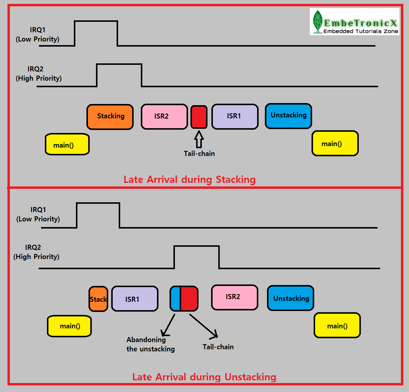
Late arrival
Tail-chaining technology in the NVIC supports interrupts that occur back-to-back, but there could be cases where higher priority interrupts could also occur during the stacking (Push) or unstacking (Pop) stages of the interrupt being serviced. In case of the late arrival of a higher priority interrupt during the execution of the stacking registers for a previous interrupt, the NVIC immediately fetches a new vector address to service the higher priority pending interrupt. In case of the late arrival of a higher priority interrupt during the execution of the unstacking (restore or pop) registers, NVIC abandons an unstacking (restore or pop) and services the new interrupt immediately. Check the below image for your reference.
|
|
|
Power management through NVIC
The NVIC also implements the power management scheme of the Cortex-M3 and M4 processor that supports integrated sleep modes. The Sleep Now mode is invoked by either the Wait For Interrupt (WFI) or the Wait For Event (WFE) instructions that immediately put the core into a low-power state pending an exception. The Sleep On Exit mode puts the system into a low-power mode as soon as it exits the lowest priority interrupt-service routine. The core stays in a sleep state until another exception is encountered. Since only an interrupt can exit this mode, the system state is not restored. If we set the SLEEPDEEP bit of the system control register, it can be used to clock gate the core and other system components for optimal power savings. The NVIC also integrates a System Tick (SysTick) timer, which is a 24-bit count-down timer that can be used to generate interrupts at regular time intervals, proving an ideal heartbeat to drive a Real-Time OS or other scheduled tasks.
Please read the other STM32 Tutorials.
You can also read the below tutorials.
Reference
- https://www.nxp.com/docs/en/data-sheet/LPC2141_42_44_46_48.pdf
- https://www.nxp.com/docs/en/user-guide/UM10139.pdf
- https://www.nxp.com/docs/en/user-guide/UM10120.pdf
- https://developer.arm.com/documentation/ddi0181/e/
- https://www.st.com/resource/en/application_note/cd00165641-str91x-interrupt-management-stmicroelectronics.pdf
- http://users.ece.utexas.edu/~valvano/Volume1/E-Book/C12_Interrupts.htm
- https://www.ti.com/lit/an/spna218/spna218.pdf?ts=1624003748070&ref_url=https%253A%252F%252Fwww.google.com%252F
- https://community.arm.com/developer/ip-products/processors/b/processors-ip-blog/posts/beginner-guide-on-interrupt-latency-and-interrupt-latency-of-the-arm-cortex-m-processors
- https://community.arm.com/developer/ip-products/processors/f/cortex-m-forum/4557/cortex-m4-exception-return-sequence
Embedded Software | Firmware | Linux Devic Deriver | RTOS
Hi, I am a tech blogger and an Embedded Engineer. I am always eager to learn and explore tech-related concepts. And also, I wanted to share my knowledge with everyone in a more straightforward way with easy practical examples. I strongly believe that learning by doing is more powerful than just learning by reading. I love to do experiments. If you want to help or support me on my journey, consider sharing my articles, or Buy me a Coffee! Thank you for reading my blog! Happy learning!
