This article is a continuation of the Series on Linux Device Drivers and carries the discussion on Linux device drivers and their implementation. The aim of this series is to provide easy and practical examples that anyone can understand. This is the GPIO Linux Device Driver Basics using Raspberry PI – Linux Device Driver Tutorial Part 35.
Learn how to implement a GPIO Linux device driver using Raspberry Pi. This tutorial covers Raspberry Pi GPIO basics, step-by-step code examples, and practical insights into controlling GPIO pins. Explore the Linux kernel’s GPIO API and discover how to interact with hardware. Perfect for developers and hobbyists.
In our previous tutorials, we have just used the Laptop or Desktop to learn the Linux Device Drivers. That will be useful for beginners who want to learn the device drivers without hardware.
However, many followers of EmbeTronicX have requested us to provide the Linux Device Driver tutorials using real hardware. So we have come up with the Raspberry Pi.
Many of you know about Raspberry Pi. So I don’t want to waste your time explaining that. We are using the Raspberry PI 4 Model B for our tutorials.
|
|
|
I have not explained what is GPIO and its types. You can always refer to this article where we have explained in-depth GPIO concepts like open-drain and push-pull GPIO.
You can also read, the I2C client device driver, I2C bus driver, Sysfs, Procfs, Workqueue, Completion, Softirq, and threaded IRQ in the Linux device driver.
Table of Contents
GPIO Linux Device Driver Basic using Raspberry PI
Hardware Required
- Raspberry Pi
- Breadboard
- Resistor
- LED
Bring up Raspberry PI
- Install Raspberry Pi OS (32-bit) with the desktop on the SD card.
- Then install the kernel header using
sudo apt install raspberrypi-kernel-headers
For your information, In my Raspberry PI 4 board, kernel 5.4.51-v7l+ is installed.
Now we are ready to write the GPIO Linux Device Driver. Before we start, we will discuss the GPIO API available in the Linux kernel.
Accessing the GPIO in Linux Kernel
If anyone wants to access the GPIO from the Kernel GPIO subsystem, they have to follow the below steps.
|
|
|
- Verify whether the GPIO is valid or not.
- If it is valid, then you can request the GPIO from the Kernel GPIO subsystem.
- Export the GPIO to sysfs (This is optional).
- Set the direction of the GPIO
- Make the GPIO to High/Low if it is set as an output pin.
- Set the debounce interval and read the state if it is set as an input pin. You enable IRQ also for edge/level triggered.
- Then release the GPIO while exiting the driver or once you are done.
The APIs used to do the above steps are given below. Keep reading guys.
GPIO APIs in Linux kernel
Already Kernel GPIO subsystems have provided the APIs to access the GPIOs. We will explain them one by one and its uses. Let’s go.
You need to include the GPIO header file given below.
#include <linux/gpio.h>
Validate the GPIO
Before using the GPIO, we must check whether the GPIO that we are planning to use is valid or not. To do that we have to use the below API.
|
|
|
bool gpio_is_valid(int gpio_number);
Where,
It returns |
This API determines whether the GPIO number is valid or not. Sometimes this call will return false even if you send a valid number. Because that GPIO pin might be temporarily unused on a given board.
Request the GPIO
Once you have validated the GPIO, then you can request the GPIO using the below APIs.
|
|
|
|
where,
It returns 0 in success and a negative number in failure. |
Note: GPIOs must be allocated before use.
There are other variants also available. You can use any one of them based on your need.
int gpio_request_one(unsigned gpio, unsigned long flags, const char *label);– Request one GPIO.int gpio_request_array(struct gpio *array, size_t num);– Request multiple GPIOs.
Export the GPIO
For debugging purposes, you can export the GPIO which is allocated using the gpio_request()to the sysfs using the below API.
|
where,
Returns zero on success, else an error. |
Once you export the GPIO, you can see the GPIO in /sys/class/gpio/*. There you can the GPIO’s value, etc. The example is given below.
Unexport the GPIO
If you have exported the GPIO using the gpio_export(), then you can unexport this using the below API.
|
Where,
|
Set the direction of the GPIO
When you are working on the GPIOs, you have to set the GPIO as output or input. The below APIs are used to achieve that.
| This API is used to set the GPIO direction as input.
Where,
Returns zero on success, else an error. |
||
This API is used to set the GPIO direction as output.
Where,
Returns zero on success, else an error. |
Change the GPIO value
Once you set the GPIO direction as an output, then you can use the below API to change the GPIO value.
|
|
|
|
where,
|
Read the GPIO value
You can read the GPIO’s value using the below API.
|
where,
It returns the GPIO’s value. 0 or 1. |
GPIO Interrupt (IRQ)
This concept is part of the next tutorial, where we discussed GPIO interrupts in detail.
Release the GPIO
Once you have done with the GPIO, then you can release the GPIO which you have allocated previously. The below API helps in that case.
|
where,
|
There are other variants also available. You can use any one of them based on your need.
void gpio_free_array(struct gpio *array, size_t num);– Release multiple GPIOs.
Now we have seen the APIs that are available in the GPIO subsystem. Now let’s see the GPIOs available in Raspberry Pi.
GPIO Raspberry PI Tutorial
40-pins are there in the Raspberry Pi 4 Model B. You can refer here for the GPIO pinouts and their details.
GPIO Programming Example
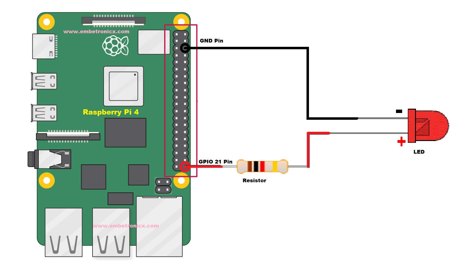
This is a very basic GPIO tutorial. So I am not going to add all the functionalities to this driver. I will connect the one LED in the GPIO 21. And I will turn ON the LED by writing “1” to the driver. If I write “0”, then the LED will go OFF.
|
|
|
Connection Diagram
Driver Source Code
[Get the source code from GitHub]
/***************************************************************************//**
*  \file       driver.c
*
*  \details    Simple GPIO driver explanation
*
*  \author     EmbeTronicX
*
*  \Tested with Linux raspberrypi 5.4.51-v7l+
*
*******************************************************************************/
#include <linux/kernel.h>
#include <linux/init.h>
#include <linux/module.h>
#include <linux/kdev_t.h>
#include <linux/fs.h>
#include <linux/cdev.h>
#include <linux/device.h>
#include <linux/delay.h>
#include <linux/uaccess.h>  //copy_to/from_user()
#include <linux/gpio.h>     //GPIO
#include <linux/err.h>
//LED is connected to this GPIO
#define GPIO_21 (21)

dev_t dev = 0;
static struct class *dev_class;
static struct cdev etx_cdev;

static int __init etx_driver_init(void);
static void __exit etx_driver_exit(void);


/*************** Driver functions **********************/
static int etx_open(struct inode *inode, struct file *file);
static int etx_release(struct inode *inode, struct file *file);
static ssize_t etx_read(struct file *filp,
                char __user *buf, size_t len,loff_t * off);
static ssize_t etx_write(struct file *filp,
                const char *buf, size_t len, loff_t * off);
/******************************************************/

//File operation structure
static struct file_operations fops =
{
  .owner          = THIS_MODULE,
  .read           = etx_read,
  .write          = etx_write,
  .open           = etx_open,
  .release        = etx_release,
};

/*
** This function will be called when we open the Device file
*/
static int etx_open(struct inode *inode, struct file *file)
{
  pr_info("Device File Opened...!!!\n");
  return 0;
}

/*
** This function will be called when we close the Device file
*/
static int etx_release(struct inode *inode, struct file *file)
{
  pr_info("Device File Closed...!!!\n");
  return 0;
}

/*
** This function will be called when we read the Device file
*/
static ssize_t etx_read(struct file *filp,
                char __user *buf, size_t len, loff_t *off)
{
  uint8_t gpio_state = 0;

  //reading GPIO value
  gpio_state = gpio_get_value(GPIO_21);

  //write to user
  len = 1;
  if( copy_to_user(buf, &gpio_state, len) > 0) {
    pr_err("ERROR: Not all the bytes have been copied to user\n");
  }

  pr_info("Read function : GPIO_21 = %d \n", gpio_state);

  return 0;
}

/*
** This function will be called when we write the Device file
*/
static ssize_t etx_write(struct file *filp,
                const char __user *buf, size_t len, loff_t *off)
{
  uint8_t rec_buf[10] = {0};

  if( copy_from_user( rec_buf, buf, len ) > 0) {
    pr_err("ERROR: Not all the bytes have been copied from user\n");
  }

  pr_info("Write Function : GPIO_21 Set = %c\n", rec_buf[0]);

  if (rec_buf[0]=='1') {
    //set the GPIO value to HIGH
    gpio_set_value(GPIO_21, 1);
  } else if (rec_buf[0]=='0') {
    //set the GPIO value to LOW
    gpio_set_value(GPIO_21, 0);
  } else {
    pr_err("Unknown command : Please provide either 1 or 0 \n");
  }

  return len;
}

/*
** Module Init function
*/
static int __init etx_driver_init(void)
{
  /*Allocating Major number*/
  if((alloc_chrdev_region(&dev, 0, 1, "etx_Dev")) <0){
    pr_err("Cannot allocate major number\n");
    goto r_unreg;
  }
  pr_info("Major = %d Minor = %d \n",MAJOR(dev), MINOR(dev));

  /*Creating cdev structure*/
  cdev_init(&etx_cdev,&fops);

  /*Adding character device to the system*/
  if((cdev_add(&etx_cdev,dev,1)) < 0){
    pr_err("Cannot add the device to the system\n");
    goto r_del;
  }

  /*Creating struct class*/
  if(IS_ERR(dev_class = class_create(THIS_MODULE,"etx_class"))){
    pr_err("Cannot create the struct class\n");
    goto r_class;
  }

  /*Creating device*/
  if(IS_ERR(device_create(dev_class,NULL,dev,NULL,"etx_device"))){
    pr_err( "Cannot create the Device \n");
    goto r_device;
  }

  //Checking the GPIO is valid or not
  if(gpio_is_valid(GPIO_21) == false){
    pr_err("GPIO %d is not valid\n", GPIO_21);
    goto r_device;
  }

  //Requesting the GPIO
  if(gpio_request(GPIO_21,"GPIO_21") < 0){
    pr_err("ERROR: GPIO %d request\n", GPIO_21);
    goto r_gpio;
  }

  //configure the GPIO as output
  gpio_direction_output(GPIO_21, 0);

  /* Using this call the GPIO 21 will be visible in /sys/class/gpio/
  ** Now you can change the gpio values by using below commands also.
  ** echo 1 > /sys/class/gpio/gpio21/value  (turn ON the LED)
  ** echo 0 > /sys/class/gpio/gpio21/value  (turn OFF the LED)
  ** cat /sys/class/gpio/gpio21/value  (read the value LED)
  **
  ** the second argument prevents the direction from being changed.
  */
  gpio_export(GPIO_21, false);

  pr_info("Device Driver Insert...Done!!!\n");
  return 0;

r_gpio:
  gpio_free(GPIO_21);
r_device:
  device_destroy(dev_class,dev);
r_class:
  class_destroy(dev_class);
r_del:
  cdev_del(&etx_cdev);
r_unreg:
  unregister_chrdev_region(dev,1);

  return -1;
}

/*
** Module exit function
*/
static void __exit etx_driver_exit(void)
{
  gpio_unexport(GPIO_21);
  gpio_free(GPIO_21);
  device_destroy(dev_class,dev);
  class_destroy(dev_class);
  cdev_del(&etx_cdev);
  unregister_chrdev_region(dev, 1);
  pr_info("Device Driver Remove...Done!!\n");
}

module_init(etx_driver_init);
module_exit(etx_driver_exit);

MODULE_LICENSE("GPL");
MODULE_AUTHOR("EmbeTronicX <[email protected]>");
MODULE_DESCRIPTION("A simple device driver - GPIO Driver");
MODULE_VERSION("1.32");
Makefile
obj-m += driver.o

KDIR = /lib/modules/$(shell uname -r)/build


all:
    make -C $(KDIR)  M=$(shell pwd) modules

clean:
    make -C $(KDIR)  M=$(shell pwd) clean
Testing the Device Driver
- Build the driver by using Makefile (
sudo make) - Load the driver using
sudo insmod driver.ko - use
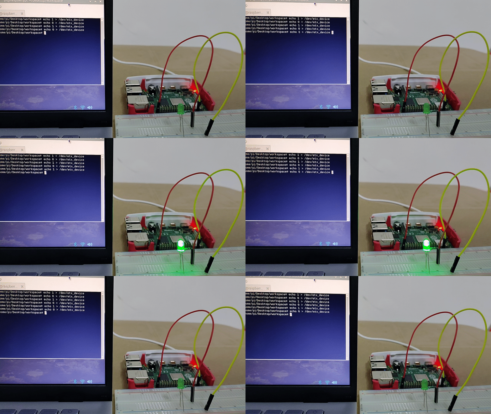
sudo suand enter the password if required to get the root permission echo 1 > /dev/etx_device[This must turn ON the LED].echo 0 > /dev/etx_device[This must turn OFF the LED].cat /dev/etx_device[Read the GPIO value].
Since we are exporting the GPIO 21 to the sysfs using gpio_export(), the below steps also should work.
echo 1 > /sys/class/gpio/gpio21/value[This must turn ON the LED].echo 0 > /sys/class/gpio/gpio21/value[This must turn OFF the LED].cat /sys/class/gpio/gpio21/value[Read the GPIO value].
GPIO Linux Device Driver – Output Video
Click here if you don’t see the output gif
|
|
|
This is a straightforward GPIO Linux Device driver tutorial to give a basic idea about the GPIO driver. In our next tutorial, we will see how to handle the inputs.
Please find the other Linux device driver tutorials here.
You can also read the below tutorials.

Embedded Software | Firmware | Linux Devic Deriver | RTOS
Hi, I am a tech blogger and an Embedded Engineer. I am always eager to learn and explore tech-related concepts. And also, I wanted to share my knowledge with everyone in a more straightforward way with easy practical examples. I strongly believe that learning by doing is more powerful than just learning by reading. I love to do experiments. If you want to help or support me on my journey, consider sharing my articles, or Buy me a Coffee! Thank you for reading my blog! Happy learning!


