Generally, we have many displays available in the market like OLED, LCD display, LED Display, etc. We cannot make those displays in our home. But there is one display called LED matrix display which is used widely in the industry. We can make the LED matrices in our home. We are going to see how to make our own LED dot matrix display in this article. Let’s get started.
Table of Contents
How to make our own LED Dot Matrix?
Required Components
LEDs

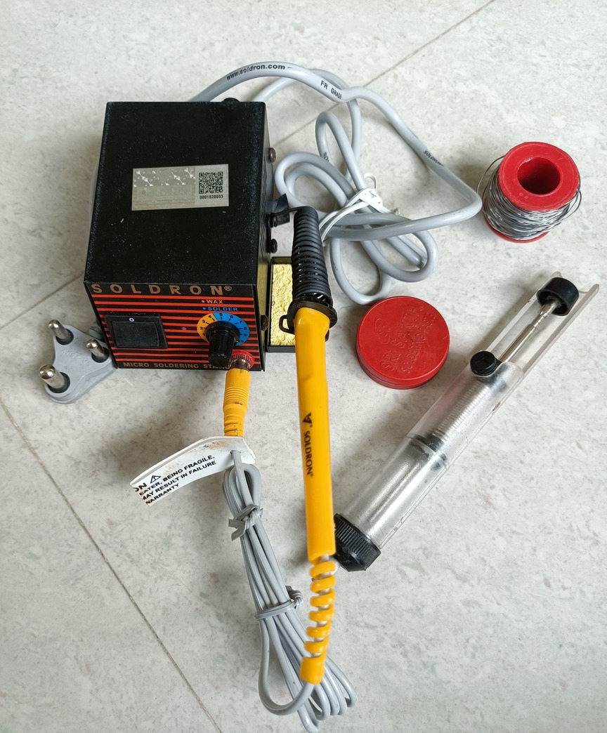
Soldering Machine
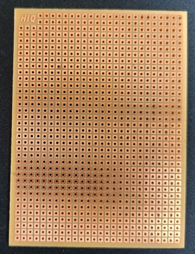
PCB Dot board
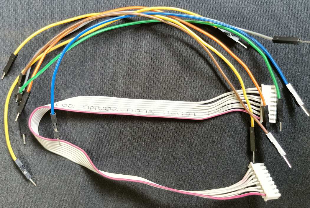
Wires
|
|
|
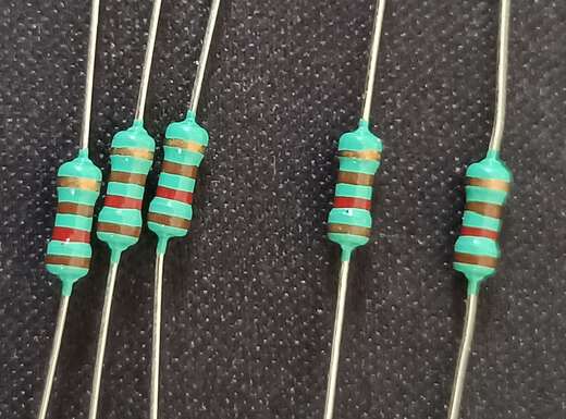
Resistors
LED (Light Emitting Diode)
Before we build the LED matrix, It’s really important to understand the LED and how it is working Yes I can hear you. Everyone already knew about the LED and its working principle. But it’s our duty to reiterate.
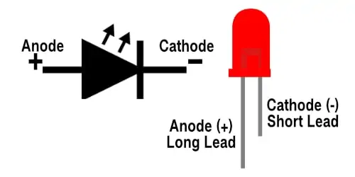
A Light Emitting Diode (LED) is a special type of PN junction diode and this can emit light when it is in the forward biased state. LED’s positive terminals are referred to as anodes. And the negative terminals are referred to as cathodes. Electricity enters through the positive side (anode) and exists through the negative side (cathode). Simply, every LED has an anode and a cathode and when the current flows unidirectionally through it, light is emitted as a result.
Now, we will come to the LED matrix.
|
|
|
LED Dot Matrix
If you arrange the LEDs into matrix format, then we can call that as a LED matrix. In this article, we are going to make a 5×5 LED dot matrix. (Note: the concept is same for other matrix formats like 5 x 7, 8 x 8, 16 x 16, 32 x 32, etc. You will have to increase the LED numbers and connect it.)
Matrix displays typically don’t have individual pins for each LED. Instead, internally the LEDs are connected in a grid pattern, exposing only the row and column terminals.
There are two types of LED matrix connections that we can build.
- Cathode Row, Anode Column (Common Row Cathode)
- Anode Row, Cathode Column (Common Row Anode)
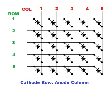
Cathode Row, Anode Column (Common Row Cathode)
In this method, Cathodes will be connected to each row and Anodes will be connected to each column. Please refer to the below image for a better understanding. In this method, the current sources (high or positive voltage) are given to Rows 1-5 and the current sinks (low or negative voltage or ground) are given to columns 1-5.
|
|
|
Anode Row, Cathode Column (Common Row Anode)
In this method, Anodes will be connected to each row and Cathodes will be connected to each column. Please refer to the below image for a better understanding. In this method, the current sources (high or positive voltage) are given to Columns 1-5 and the current sinks (low or negative voltage or ground) are given to rows 1-5.
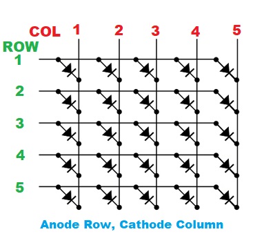
Note: In this article, we are going to build Anode Row, Cathode Column (Common Row Anode).
Build LED Matrix
There are many LED matrices that are available already in the market. If you don’t want to use it then you can create your own LED matrix.
|
|
|
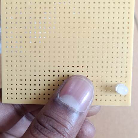
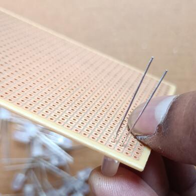
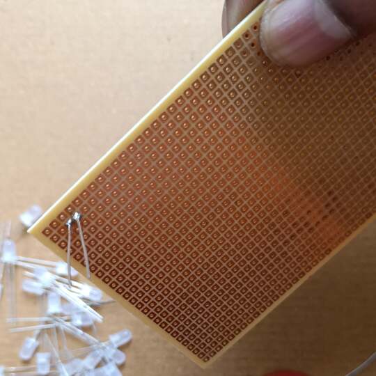
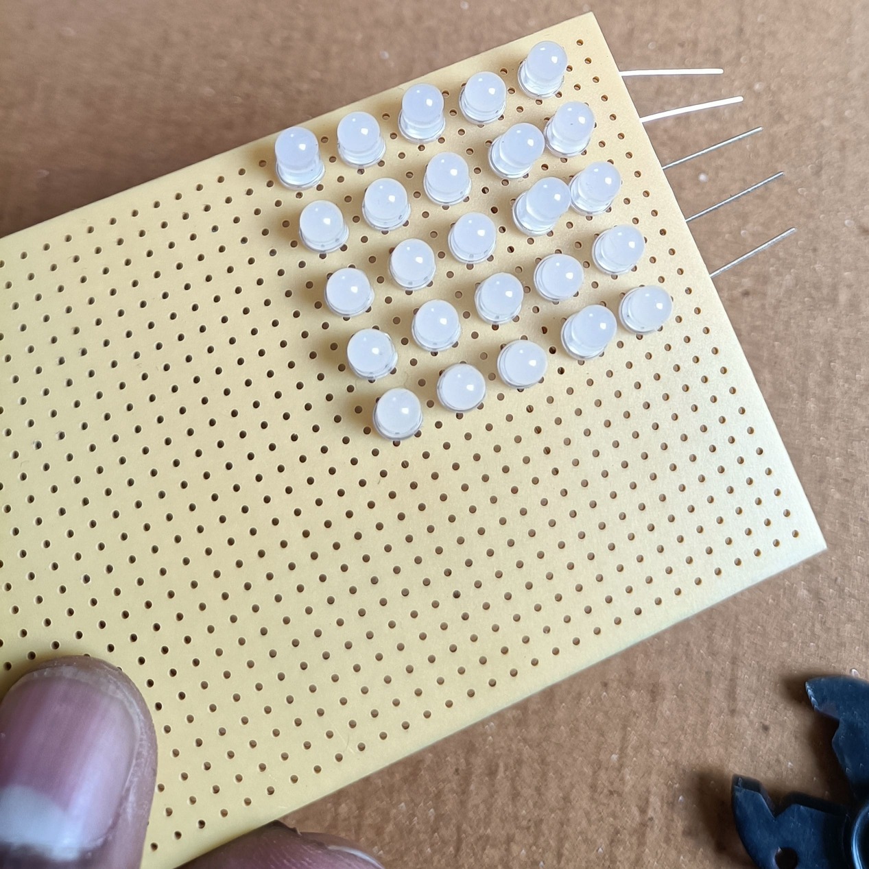
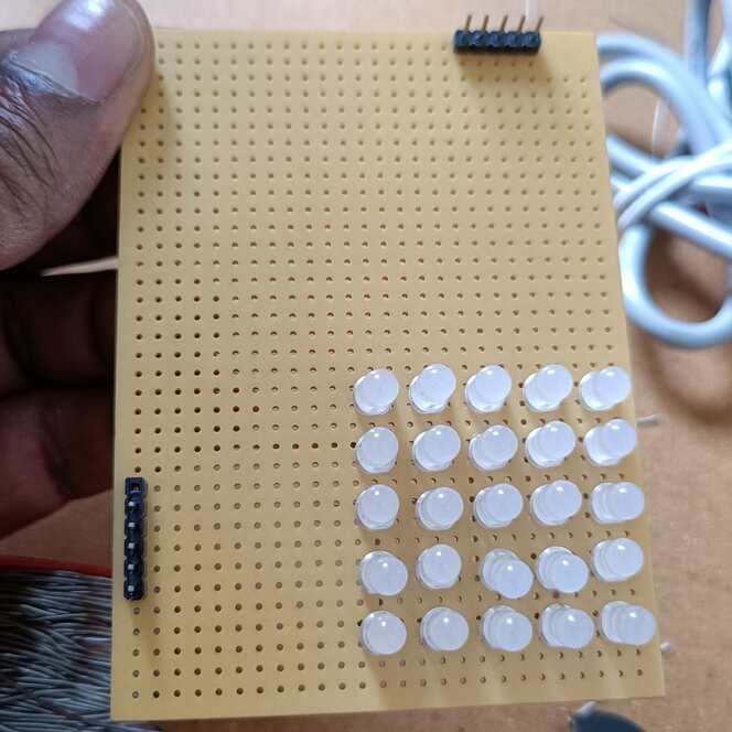
Okay, Now we will make our own LED Dot Matrix. First, take the LED and put that into the PCD dot board and solder that LED. Please make sure you note which side is the cathode(-) and the anode(+).
 |
 |
 |
 |
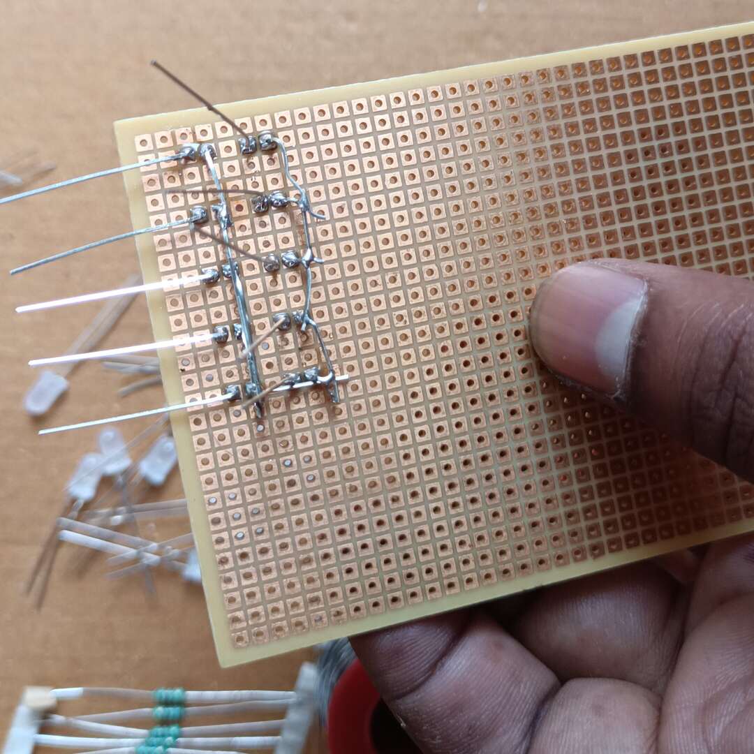
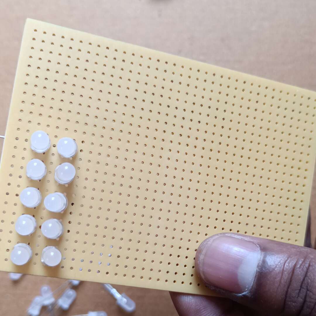
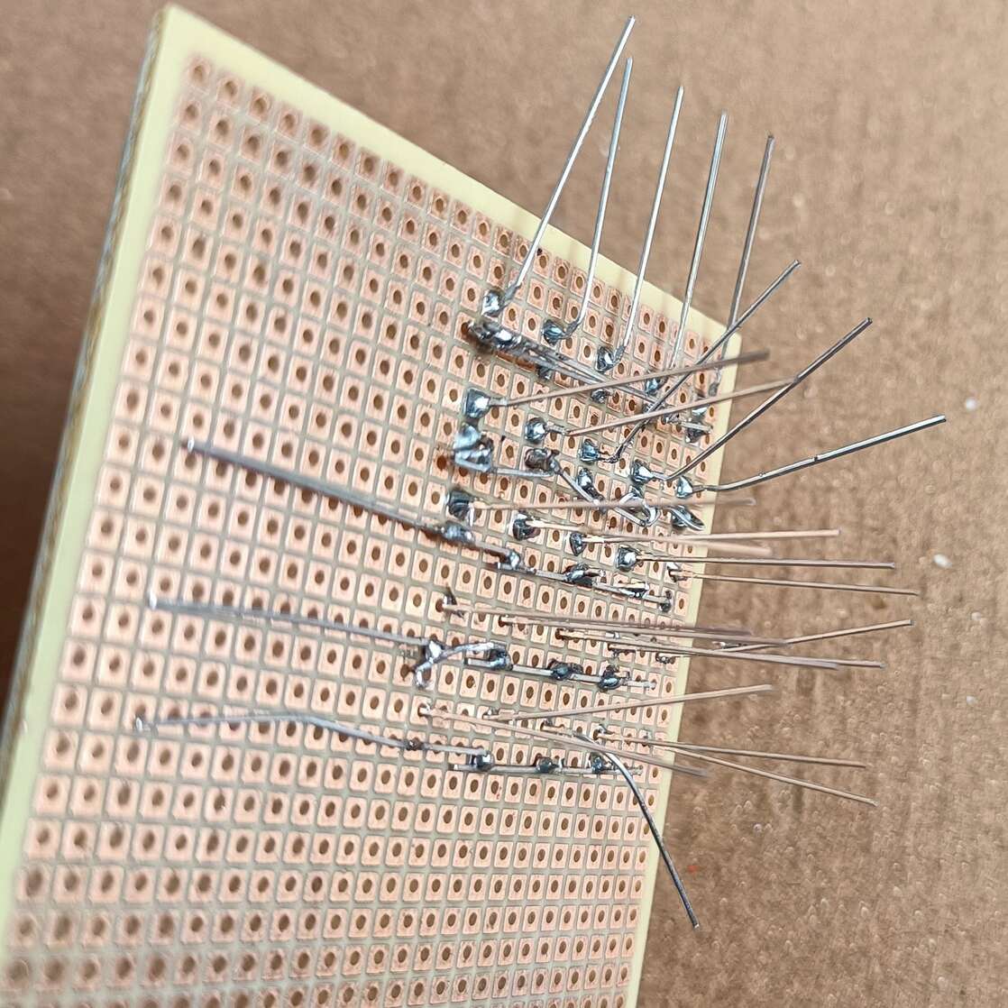
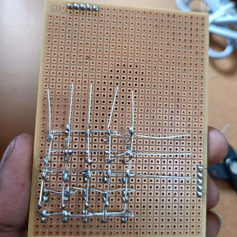
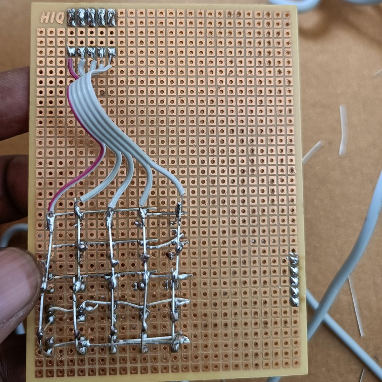
We are going to make a common anode LED matrix. So, arrange the LEDs in a proper fashion. The anode should be at the top and the cathode should be at the bottom. Then solder the LEDs one by one and connect the rows (anode) together.
 |
 |
 |
 |
 |
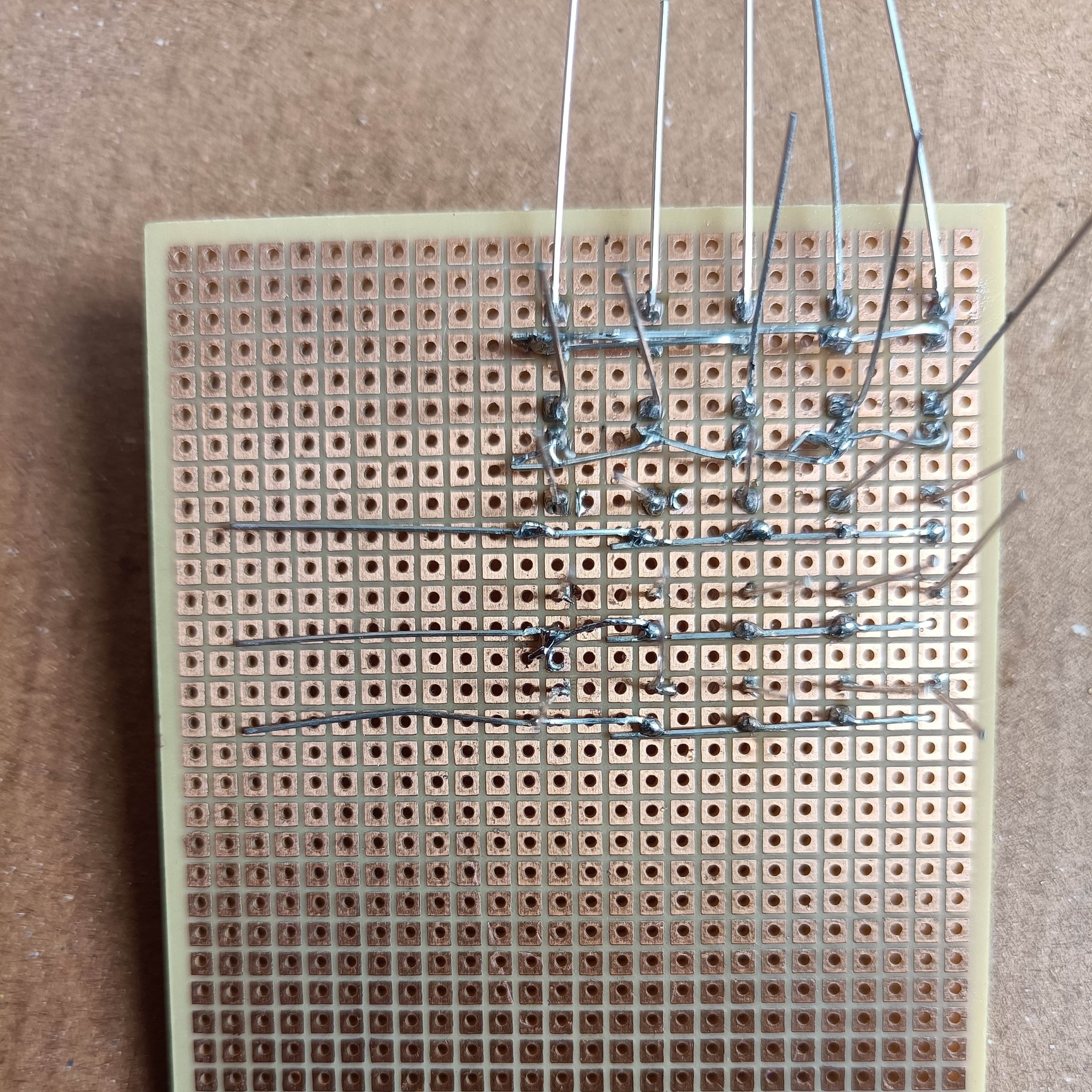
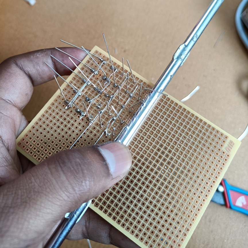
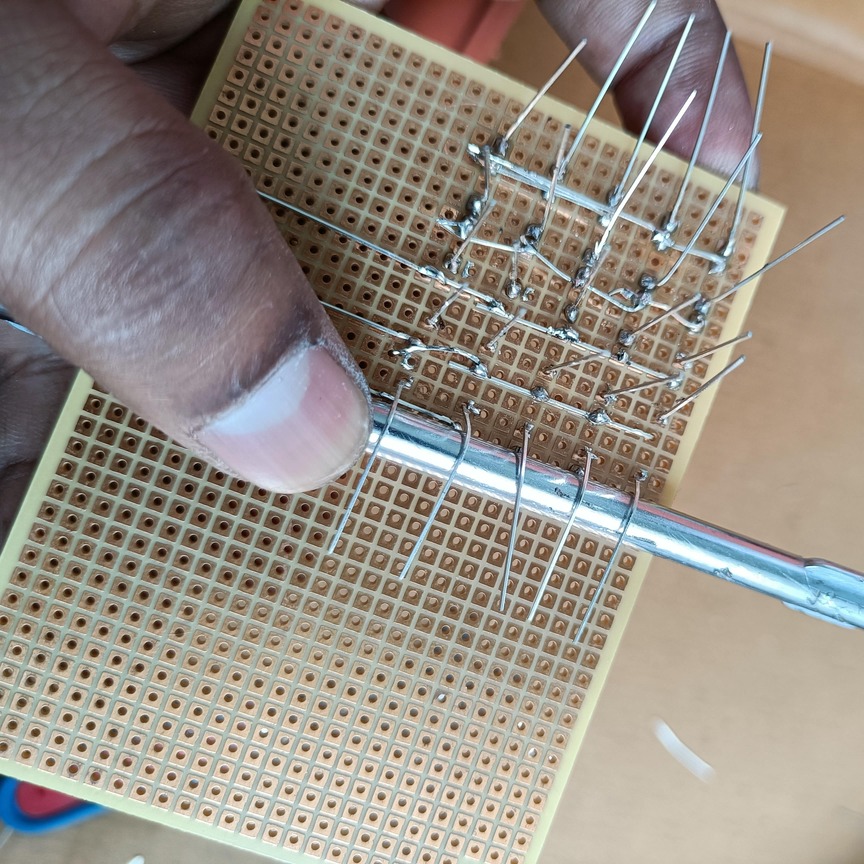
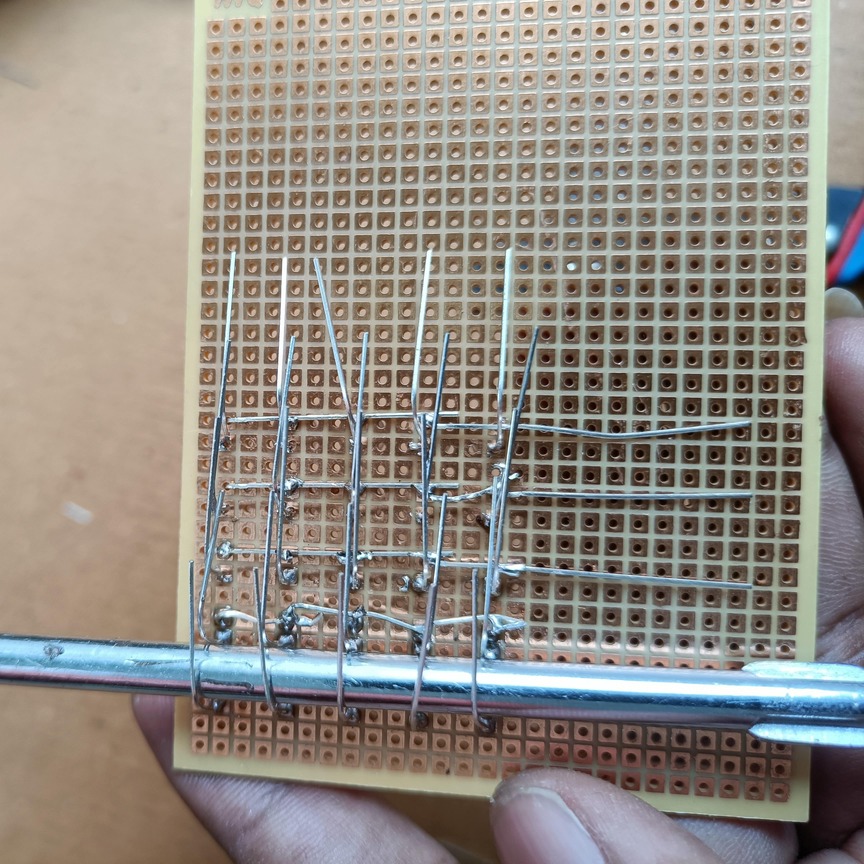
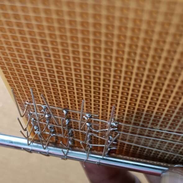
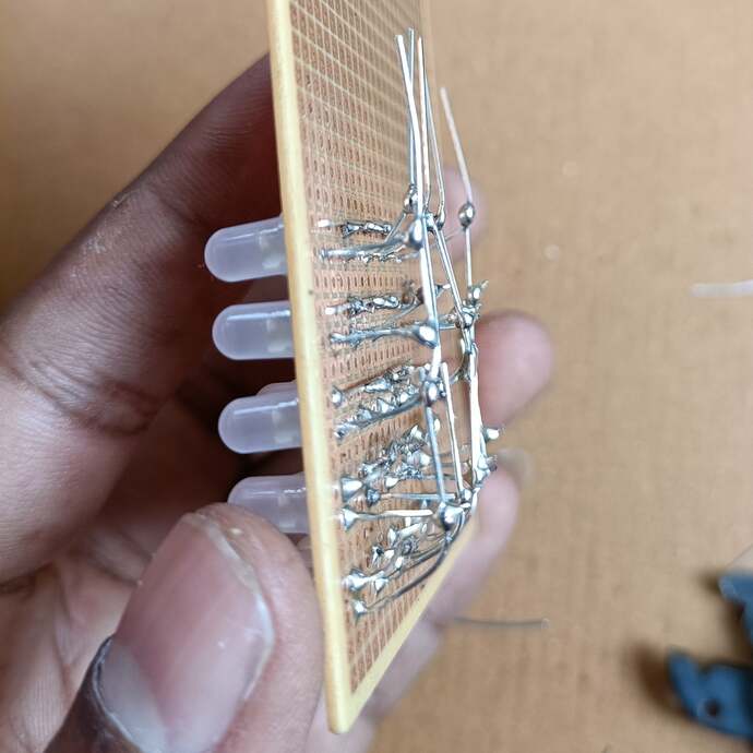
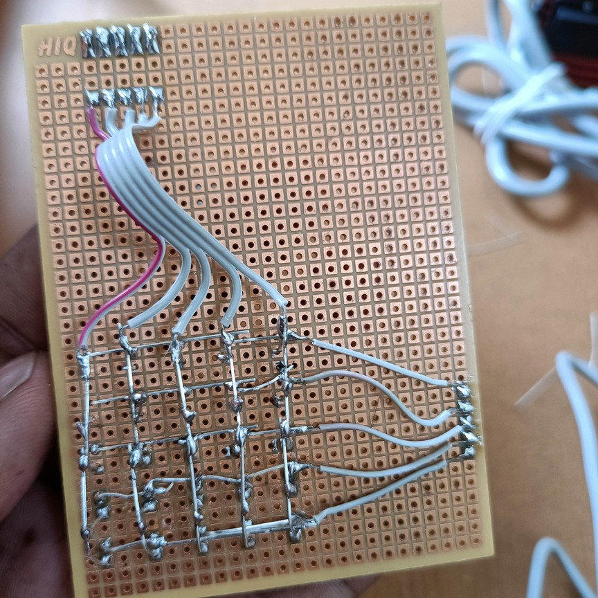
Now, we will start soldering the cathode columns. While we are doing this, the anodes should not touch the cathodes. Here, we are using a screwdriver to assist with the bending process. Then solder those columns.
 |
 |
 |
 |
 |
 |
 |
 |
Now let’s solder the connector.
 |
 |
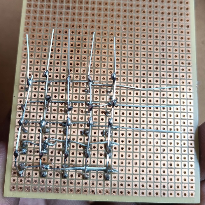
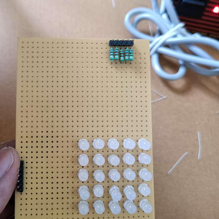
Now we will solder the resistors. In this led matrix, we have used 120ohm. You can calculate the resistance for your circuit and use those resistors. And also we have connected the resistors to the cathode (column). You can connect those resistors to the anode (rows).
|
|
|
 |
 |
Let’s connect the column and row to the connector.
 |
 |
Accessing individual LEDs
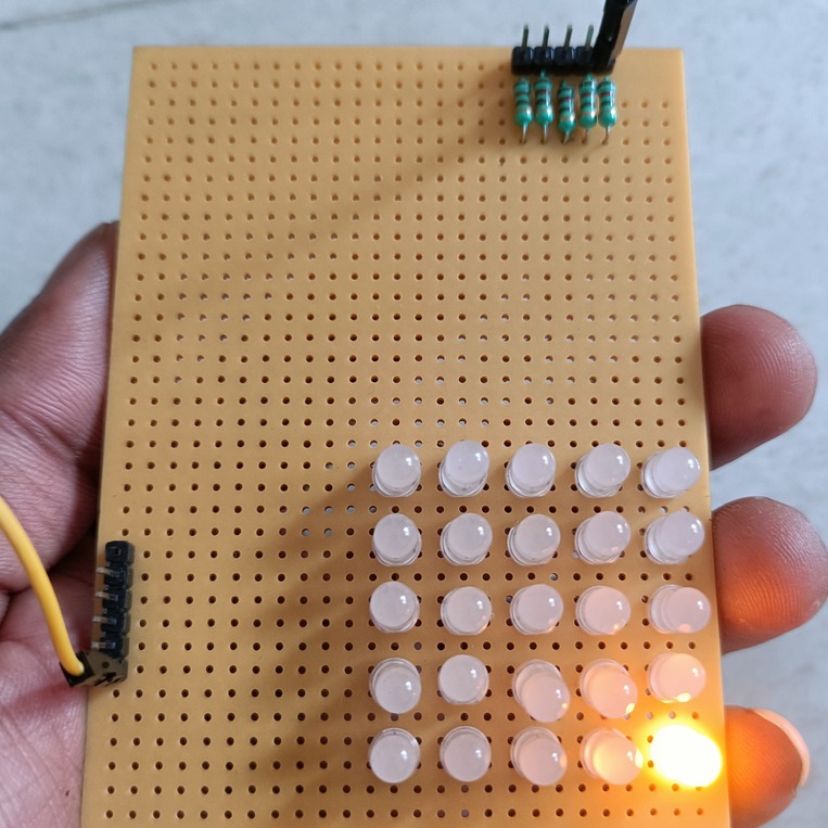
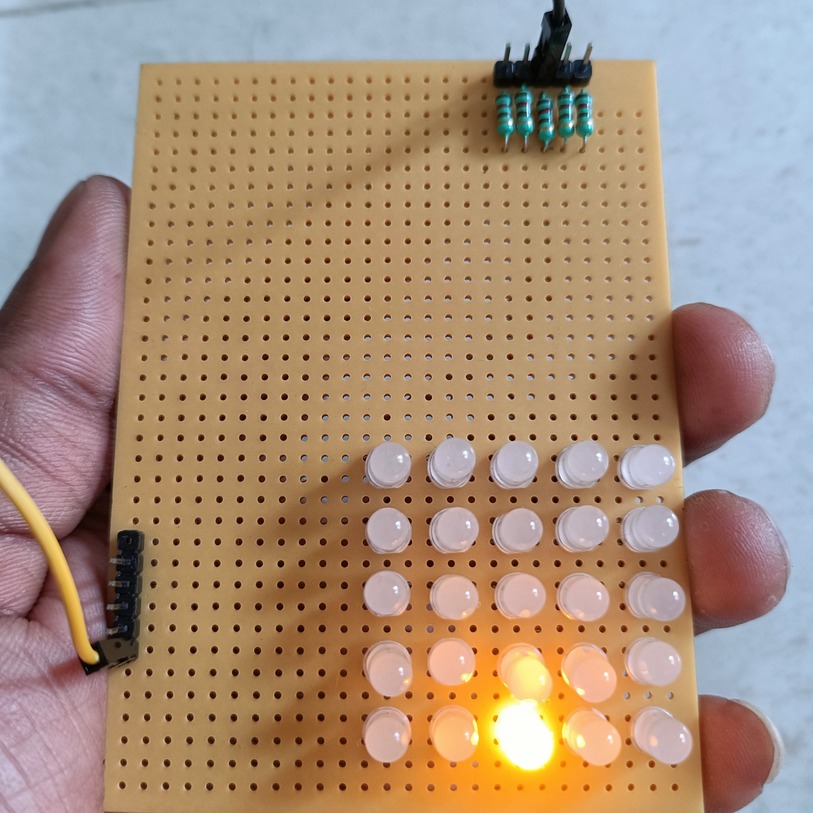
We connected all the LEDs. Now we will test the led matrix. You turn on an individual LED by setting its row and column pins to the proper polarity. Connect the positive supply to the row and GND to the column. The respective LED must glow.
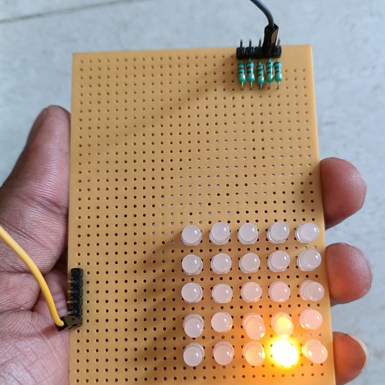
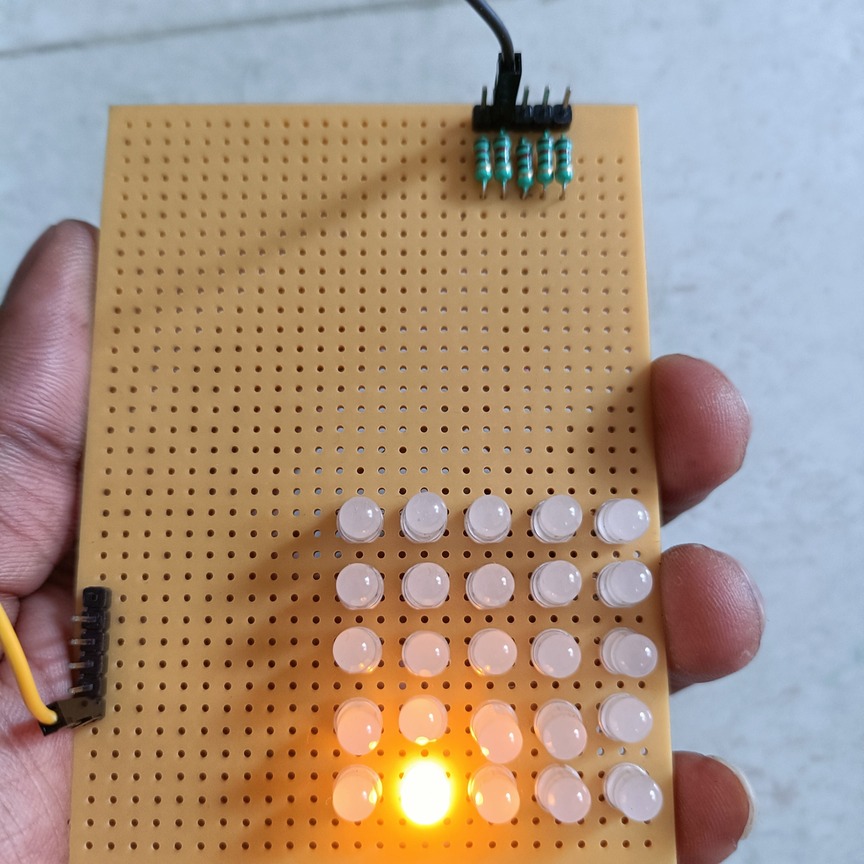
For example, refer to the first image. We have given GND to column 5 and 3v to row 5. So, only the (5,5) LED will get both positive and GND for the LED’s anode and cathode respectively. So, the LED is glowing. In the second image, we have given GND to column 4 and 3v to row 4. So, the (4,4) LED will glow. If you connect 3v to all the rows and GND to all the columns, then all the LEDs will glow.
 |
 |
 |
 |
 |
I hope you might solder better than us. You can follow this same method and increase the number of LEDs to make 8×8, 5×7, and 16×16 matrices.
Applications of LED Matrix Display
LED matrix display is used in many fields.
|
|
|
- Industrial Controls
- Medical Equipment
- Communications Equipment
- Test and Measurement Equipment
- Security Electronics
- Life Safety Equipment
- Large Panel Indicators
- Meter Displays
- Information displays
Advantages
- It is cheap.
- Long life.
- High brightness compared to other displays.
- It will be visible even at Long distances.
- It is environmentally friendly because it has no mercury or any other hazardous material.
- It has a low temperature.
Disdvantages
- Huge size.
- Low resolution.
- Not suitable for close viewing.
You can also read the below tutorials.
Embedded Software | Firmware | Linux Devic Deriver | RTOS
Hi, I am a tech blogger and an Embedded Engineer. I am always eager to learn and explore tech-related concepts. And also, I wanted to share my knowledge with everyone in a more straightforward way with easy practical examples. I strongly believe that learning by doing is more powerful than just learning by reading. I love to do experiments. If you want to help or support me on my journey, consider sharing my articles, or Buy me a Coffee! Thank you for reading my blog! Happy learning!
