
In general, whenever we learn a new programming language we used to write the “Hello World” program first. Likewise in the microcontroller, we try the LED Blinking program. To blink the LED, we need to access the GPIO. If you are a programmer, you can just write “1” to the GPIO pin to make it high and write “0” to make the gpio pin low. But do you know how that gpio is working internally? and gpio types? Yeah in this Understanding the Microcontroller GPIO – GPIO Working Explained article, we will explain all those concepts. As a firmware engineer, you must master these concepts as your most of the work will be writing bare metal code or driver code and as an embedded application developer, you should know these concepts. Let’s get started.
Table of Contents
Understanding the Microcontroller GPIO – GPIO Working Explained
What is GPIO?
GPIO or General Purpose Input Output is one of the most frequent terms which you might have come across with. A GPIO is a signal pin on an integrated circuit or board that can be used to perform digital input or output functions. The GPIO behavior (input or output) is controlled at the run time by the application software/firmware by setting a few registers. Typical applications include reading/writing values from/to analog or digital sensors/devices, driving a led, driving a clock for I2C communication, Generating triggers for external components, Issuing Interrupts, etc.
All the microcontrollers will be having a few registers to control the gpio functions. Those register names will vary based on the microcontroller. In this article, we are not going to focus on the registers of the particular microcontroller. The concepts that are explained in this article are generic and can be applied to any microcontroller you have.
What is the GPIO port?
There will be many GPIO pins in the microcontroller. Those pins are grouped by some name. So, that one group is called GPIO port. Simply, the collection of GPIOs is called GPIO port. For example, If you take the STM32F401VE microcontroller, it has 5 GPIO ports (PORT A, PORT B, PORT C, PORT D, PORT E). Each port has 16 GPIO pins. Like this, other microcontrollers will have few GPIO ports.
GPIO Modes
Generally, GPIO can be used in multiple ways.
The Input and Output modes will be further classified. But before seeing that, we will see the basic GPIO working in Input and Output mode.
Let’s learn how the input and output mode works at the circuit level. The below image shows the simple implementation of a GPIO pin in a microcontroller.

Each GPIO pin consists of two buffers – Input buffer and Output buffer along with one enable line. When the enable line is 0, the output buffer gets activated and the input buffer will be deactivated. When the enable line is 1, then the output buffer gets deactivated and the input buffer gets activated.
GPIO act as Output
First, we will see how the GPIO works in output mode. If you make the enable line as 0, this will activate the output buffer and deactivate the input buffer.
The output buffer is connected to the two CMOS Transistors. CMOS technology uses both N-type (NMOS) and P-type (PMOS) transistors and it is connected like the below diagram.

GPIO High
In the above image, T1 is the PMOS transistor and T2 is the NMOS transistor. When we write 1 from our code, the first inverter will make it as 0. So, the PMOS transistor (T1) will be activated and the NMOS transistor (T2) will be deactivated. Finally, T1 will take the Vcc and give it to the GPIO pin. If we connect the LED now, it will be ON. The below diagram explains the concept that we talked about now.

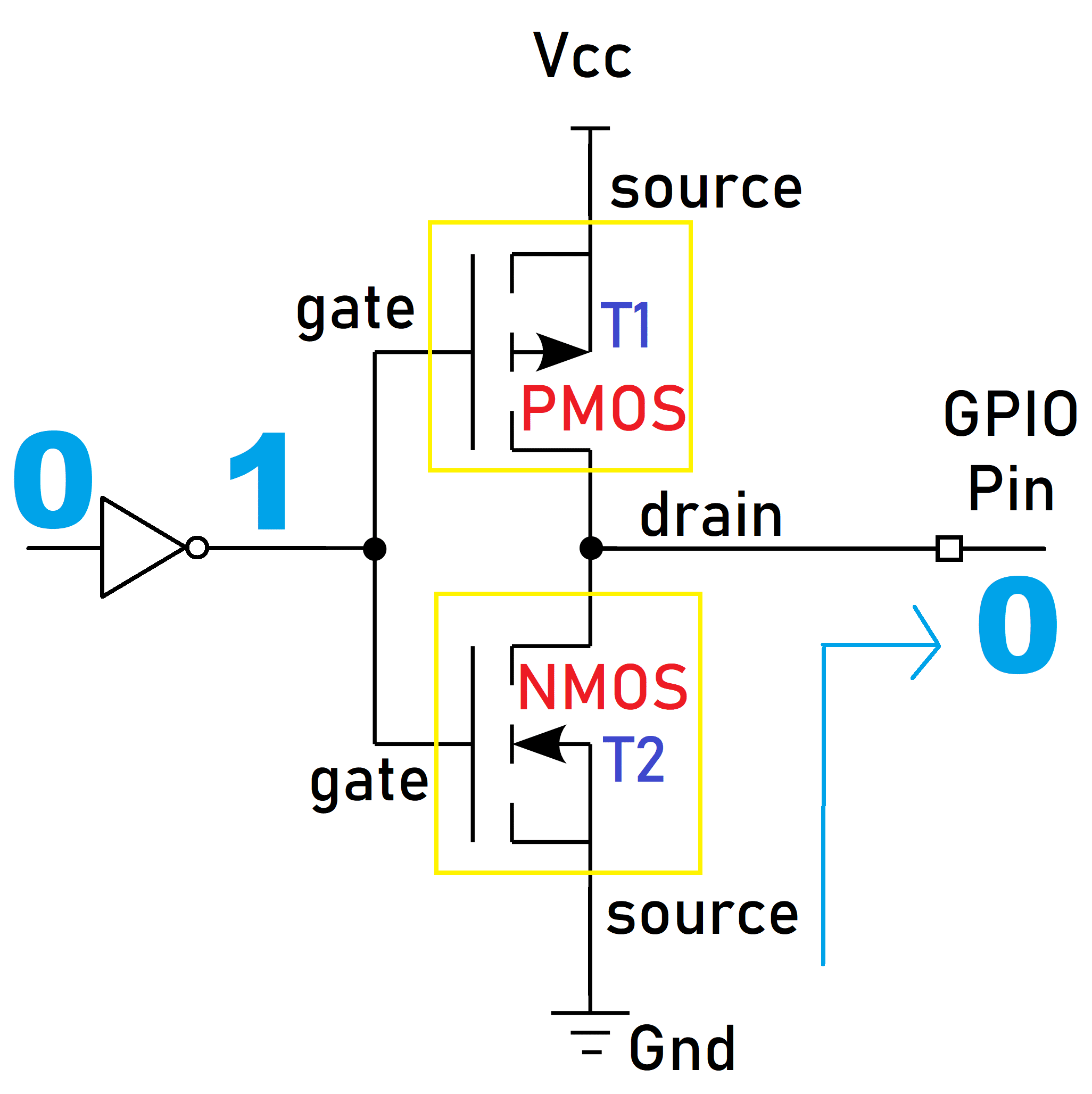
Gpio Low
When we write 0 from our code, the first inverter will make it as 1. So, the PMOS transistor (T1) will be deactivated and the NMOS transistor (T2) will be activated. Finally, T2 will take the Gnd and give it to the GPIO pin. If we connect the LED now, it will be turned OFF. The below diagram explains the concept that we talked about now.
GPIO act as Input
The input buffer is involved in the input mode. If you make the enable line as 1, this will deactivate the output buffer and activate the input buffer. GPIO Input buffer also has CMOS where NMOS and PMOS are connected like the output buffer. But here, the gate is connected to the GPIO pin, and the drain is connected to the processor. You can check the below diagram.

When the external device is writing 1 to the GPIO pin, the first inverter will make it as 0. So, the PMOS transistor (T1) will be activated and the NMOS transistor (T2) will be deactivated. Finally, T1 will take the Vcc and give it to the processor. So, we will get 1 in our software. When the external device is writing 0 to the GPIO pin, the first inverter will make it as 1. So, the PMOS transistor (T1) will be deactivated and the NMOS transistor (T2) will be activated. Finally, T2 will take the Gnd and give it to the processor. So, we will get 0 in our software. The below diagram will help you understand this concept.

We have understood how the GPIO is working in the microcontroller. Now it is time to see the different types of Input and output modes.
GPIO Input Modes
The GPIO is used to read the electrical signal in the pin when it is configured as an input. In general, GPIO inputs are primarily configured in one of three ways:
High-impedance
High-impedance or HI-Z State of a GPIO is nothing but keeping the pin floating by not connecting to either HIGH (Vcc) or LOW (GND) Voltage levels. That means the pin is left open. So, this state is also called a floating state. Its state is indeterminate unless it is driven high or low externally.
Whenever the microcontroller is powered ON, the GPIO pins are by default in this HIGH impedance state input mode. You only want to configure a pin as floating if you know it will be driven externally. Otherwise, It is recommended to keep the unused pins in either a pull-up or pull-down state to avoid leakage of current. Because Keeping the pin in a floating state can lead to leakage current, which may result in high power consumption because a floating pin is highly susceptible to picking up the noise and may result in leakage current.
If you see the below image, the GPIO pin is not connected to either Vcc or GND.

Pull-up
To avoid this HIGH impedance or floating state, a pull-up resistor is introduced. In this type, the internal pull-up resistor is connected to the pin. So, the state will be HIGH unless an external pull-down resistor is used. There will be a particular register to enable this pull-up resistor in the microcontroller. You can go through the datasheet of your microcontroller. The below image shows how the internal pullup resistor is connected.

Pull-down
To avoid this HIGH impedance or floating state, a pull-down resistor is introduced. In this type, the internal pull-down resistor is connected to the pin. So, the state will be Low unless an external pull-up resistor is used. There will be a particular register to enable this pull-down resistor in the microcontroller. You can go through the datasheet of your microcontroller. The below image shows how the internal pull-down resistor is connected.

GPIO Output Modes
The GPIO is used to drive the electrical signal (high or low) to the pin when it is configured as a output. There are primarily two configuration options for GPIO outputs:
Push-pull
This state is the default state of the GPIO output mode. The pin can “push” the signal high or “pull” it low using the PMOS transistor or NMOS transistor. There is no need for pull-up or pull-down resistors as the PMOS and NMOS transistors do that job. This concept has been already explained in the above section.
Open-drain
In GPIO output mode, the output buffer is formed using the PMOS and NMOS transistors. If you remove the PMOS transistor, then it will be an open drain output mode. See the below image. There the PMOS transistor has been removed.

When you make the NMOS to high, then it will supply a GND. The GPIO pin will be Low. When you turn off the NMOS, the GPIO will not be connected to either Vcc or GND. It will be in a floating state. So, the output will be either Low or high impedance (floating). It can pull the pin towards the ground, but it cannot drive it high. For this type of output, there needs to be an external pull-up resistor added to the circuit, which will cause the line to go high when not driven low.
The name comes from the fact that the MOSFET’s drain isn’t internally connected to anything. If you use BJT instead of MOSFET, then this is called an Open collector.
Open drain outputs are most commonly used in communication interfaces where multiple devices are connected on the same line (e.g I2C, One-Wire, etc.). When all of the outputs of the devices connected to the line are in the Hi-Z state, the line is driven to a default logic 1 level by a pull-up. Any device can pull the line to logic 0 using its open drain output and all devices can see this level.
Analog Mode
You can configure the input as an analog input. This mode connects the pin to an internal ADC (analog-to-digital converter) and allows you to read a value that represents a given voltage in a pin. The value depends on the resolution of the ADC, for example, a 12-bit ADC can have values that go from 0 to 4095. This value is mapped to a voltage that is between 0V and (usually) the voltage the microcontroller is running (3.3V for example).
When a GPIO is configured in analog mode the input pull-up/pull-down resistors are disconnected (floating).
Note that not all the GPIOs in a microcontroller can be configured as analog input. Refer to your microcontroller datasheet to know which ones can be configured as such.
Alternate function Mode
GPIO pins have the capability of providing an alternate function apart from the regular three modes. The pins are multiplexed to provide functionalities like USART Tx pin, I2C data pin, etc. There will be a separate register to set the alternate functions. Please check your microcontroller’s datasheet to get to know more about that.
You can read the STM32 GPIO tutorial, 8051 GPIO tutorial, PIC16F877a GPIO tutorial, LPC2148 GPIO tutorial, ESP32 GPIO tutorial using NuttX RTOS, and GPIO Linux Device Driver.
You can also read the below tutorials.
Embedded Software | Firmware | Linux Devic Driver | RTOS
Hi, I am a tech blogger and an Embedded Engineer. I am always eager to learn and explore tech-related concepts. And also, I wanted to share my knowledge with everyone in a more straightforward way with easy practical examples. I strongly believe that learning by doing is more powerful than just learning by reading. I love to do experiments. If you want to help or support me on my journey, consider sharing my articles, or Buy me a Coffee! Thank you for reading my blog! Happy learning!
Share this:

Discover more from EmbeTronicX
Subscribe to get the latest posts sent to your email.
Learn to new post comment