Table of Contents
Matrix Keypad – Introduction
Most of the applications of embedded systems require keypads to take the user inputs, especially in the case where an application requires more keys. With simple architecture and easy interfacing procedure, matrix keypads are replacing normal push buttons by offering more inputs to the user with the lesser I/O pins. As a Human Machine Interface (HMI) keypad plays a major role in vital microprocessor and microcontroller-based projects and equipment. Therefore, this article gives you a brief idea about the matrix keypad.
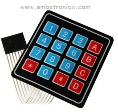
A Matrix keypad is the most commonly used input device in many of the application areas like digital circuits, telephone communications, calculators, ATMs, and so on. A matrix keypad consists of a set of push-button or switches which are arranged in a matrix format of rows and columns. These keypads are available in configurations like 3×4 and 4×4 based on the application it is implemented for.
Keypad Internal structure
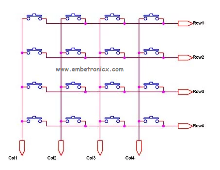
At the lowest level, keyboards are organized in a matrix of rows and columns. The CPU accesses both rows and columns through ports. When a key is pressed, a row and a column make a contact. otherwise, there is no connection between rows and columns. So this is the logic we are going to use.
Key Scanning
The status of each key can be determined by a process called Scanning. There are many methods depending on how you connect your keypad with your controller, but the basic logic is the same. For the sake of explanation, let’s assume that all the column pins (Col1 – Col4) are connected to the inputs pins and all the row pins are connected to the output pins of the microcontroller. In the normal case, all the column pins are pulled up (HIGH state) by internal or external pull-up resistors. Now we can read the status of each switch through scanning.
|
|
|
- A logic LOW is given to Row1 and others (Row2 – Row-4) HIGH
- Now each Column is scanned. If any switch belongs to the 1st row is pressed the corresponding column will pull down (logic LOW) and we can detect the pressed key.
- This process is repeated for all rows.
That’s all guys. I think you could understand the operation of the keypad. Here I show a 4×4 matrix keypad. But if you take a 3×3 or 4×3 keypad the operation will be the same. If you got an idea you can try to write coding. Thank you.
You can also read the below tutorials.
Embedded Software | Firmware | Linux Devic Deriver | RTOS
Hi, I am a tech blogger and an Embedded Engineer. I am always eager to learn and explore tech-related concepts. And also, I wanted to share my knowledge with everyone in a more straightforward way with easy practical examples. I strongly believe that learning by doing is more powerful than just learning by reading. I love to do experiments. If you want to help or support me on my journey, consider sharing my articles, or Buy me a Coffee! Thank you for reading my blog! Happy learning!
