In this tutorial, we will see what is ultrasonic sensors and the applications of ultrasonic sensors and it’s characteristics. Let’s start.
You can also read sound sensor interfacing with 8051, sound sensor interfacing with PIC16F877A, sound sensor interfacing with LPC2148, 8051 ultrasonic sensor interfacing, and LPC2148 ultrasonic sensor interfacing.
Table of Contents
What is an Ultrasonic Sensor?
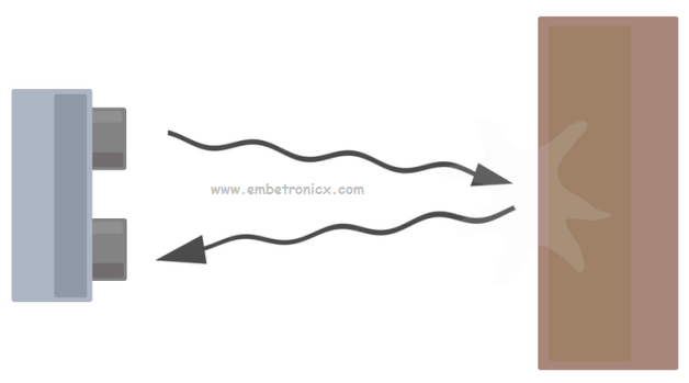
An Ultrasonic sensor is a device that can measure the distance to an object by using sound waves. It measures distance by sending out a sound wave at a specific frequency and listening for that sound wave to bounce back. By recording the elapsed time between the sound wave being generated and the sound wave bouncing back, it is possible to calculate the distance between the sonar sensor and the object.
An optical sensor has a transmitter and receiver, whereas an ultrasonic sensor uses a single ultrasonic element for both emission and reception. In a reflective model ultrasonic sensor, a single oscillator emits and receives ultrasonic waves alternately. This enables miniaturization of the sensor head.
|
|
|
Distance calculation
The distance can be calculated with the following formula:
Distance (L) = 1/2 × T × C
where L is the distance, T is the time between the emission and reception, and C is the sonic speed. (The value is multiplied by 1/2 because T is the time for the go-and-return distance.)
Since it is known that sound travels through air at about 344 m/s (1129 ft/s), you can take the time for the sound wave to return and multiply it by 344 meters (or 1129 feet) to find the total round-trip distance of the sound wave. Round-trip means that the sound wave traveled 2 times the distance to the object before it was detected by the sensor; it includes the ‘trip’ from the sonar sensor to the object AND the ‘trip’ from the object to the Ultrasonic sensor (after the sound wave bounced off the object). To find the distance to the object, simply divide the round-trip distance in half.
It is important to understand that some objects might not be detected by ultrasonic sensors. This is because some objects are shaped or positioned in such a way that the sound wave bounces off the object, but is deflected away from the Ultrasonic sensor. It is also possible for the object to be too small to reflect enough of the sound wave back to the sensor to be detected. Other objects can absorb the sound wave all together (cloth, carpeting, etc), which means that there is no way for the sensor to detect them accurately. These are important factors to consider when designing and programming a robot using an ultrasonic sensor.
|
|
|
NOTE: The accuracy of the Ultrasonic sensor can be affected by the temperature and humidity of the air it is being used in. However, for these tutorials and almost any project, you will be using these sensors in, this change inaccuracy will be negligible.
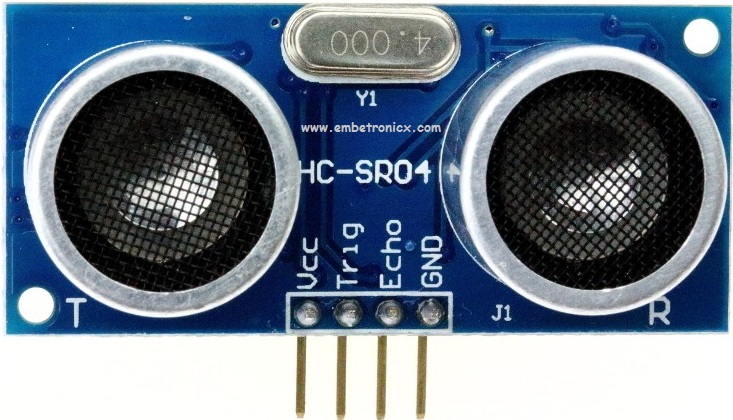
Ultrasonic Sensor – HC-SR04

Description: This is the HC-SR04 ultrasonic ranging sensor. This economical sensor provides 2cm to 400cm of non-contact measurement functionality with a ranging accuracy that can reach up to 3mm. Each HC-SR04 module includes an ultrasonic transmitter, a receiver, and a control circuit.
There are only four pins that you need to worry about on the HC-SR04: VCC (Power), Trig (Trigger), Echo (Receive), and GND (Ground). You will find this sensor very easy to set up and use for your next range-finding project!
Features
- Operating Voltage: 5V DC
- Operating Current: 15mA
- Measure Angle: 15°
- Ranging Distance: 2cm – 4m
The basic principle of work
(1) Using IO trigger for at least 10us high-level signal,
|
|
|
(2) The Module automatically sends eight 40 kHz and detects whether there is a pulse signal back.
(3) If the signal back, through a high level, the time of high output IO duration is the time from sending ultrasonic to returning.
Test distance = (high level time×velocity of sound (340M/S) / 2
Wire connection
- VCC – 5V DC supply voltage is connected to this pin.
- Trigger Pin – The trigger signal is to start the transmission of waves which must be a pulse with 10uS high time.
- Echo Pin – At this pin, the module outputs a waveform with high time proportional to the distance.
- GND – Ground is connected to this pin.
Timing diagram
The Timing diagram is shown below. You only need to supply a short 10uS pulse to the trigger input to start the ranging, and then the module will send out an 8 cycle burst of ultrasound at 40 kHz and raise its echo. The Echo is a distance object that is pulse width and the range in proportion. You can calculate the range through the time interval between sending trigger signal and receiving echo signal. Formula: uS / 58 = centimeters or uS / 148 =inch or the range = high level time * velocity (340M/S) / 2; we suggest to use over 60ms measurement cycle, in order to prevent trigger signal to the echo signal.

|
|
|
Attention
- The module is not suggested to connect directly to electric, if connected electric, the GND terminal should be connected to the module first, otherwise, it will affect the normal work of the module.
- When tested objects, the range of area is not less than 0.5 square meters, and the plane requests as smooth as possible, otherwise, it will affect the results of measuring.
You can also read the below tutorials.
Embedded Software | Firmware | Linux Devic Deriver | RTOS
Hi, I am a tech blogger and an Embedded Engineer. I am always eager to learn and explore tech-related concepts. And also, I wanted to share my knowledge with everyone in a more straightforward way with easy practical examples. I strongly believe that learning by doing is more powerful than just learning by reading. I love to do experiments. If you want to help or support me on my journey, consider sharing my articles, or Buy me a Coffee! Thank you for reading my blog! Happy learning!
