
In this tutorial, we are going to see Password Based Door Open System Using LPC2148 Project.
Table of Contents
Prerequisites
Before we will start I would suggest you to read these topics. Then only you can understand this strongly. If you already know, please go ahead.
- LPC2148 GPIO Tutorial
- LCD Interfacing with LPC2148
- Keypad Interfacing with LPC2148
- DC Motor Interfacing with LPC2148
Password Based Door Open System Using LPC2148
Introduction
In the present scenario of the world, security is a major concern for all, and the security problem is being faced by every person. The usual means of securing anything is through mechanical locks, which operate with a specific key or a few keys; but, for locking a large area many locks are necessary. However, conventional locks are heavy and do not offer the desired protection as they can be easily broken down by using some tools. Therefore, security breaching problems are associated with mechanical locks. However to decide the electronic-based locking system problems that are associated with the mechanical locks.
Nowadays, many devices’ operations are based on digital technology. For example, a token-based digital identity device. Here we will see Password Based Door Open System Using LPC2148.
Application and Advantage
- Can be used in various rooms like seminar halls, conference rooms, and study rooms in college.
- The project (password detector) can be used to automate the door locking process, so the user need not to carry the door lock keys along with them, they need to just remember the password and use it later to open the door.
- It will add good security.
Components Required
- LPC2148 Development Board
- LCD Module
- 4*3 Keypad
- DC Motor
- L293D (Motor Driver)
Software Required
- Keil IDE
Block Diagram
This project consists of blocks as a microcontroller, a keypad, an LCD, a DC motor, and a motor driver.

- The keypad is an input device that helps to enter a password to open the door.
- Then, it gives the entered code signals to the microcontroller.
- The LCD is used to indicate devices for displaying the information.
- The DC motor moves the door to open and close and the motor driver drives the motor after receiving the code signals from the microcontroller.
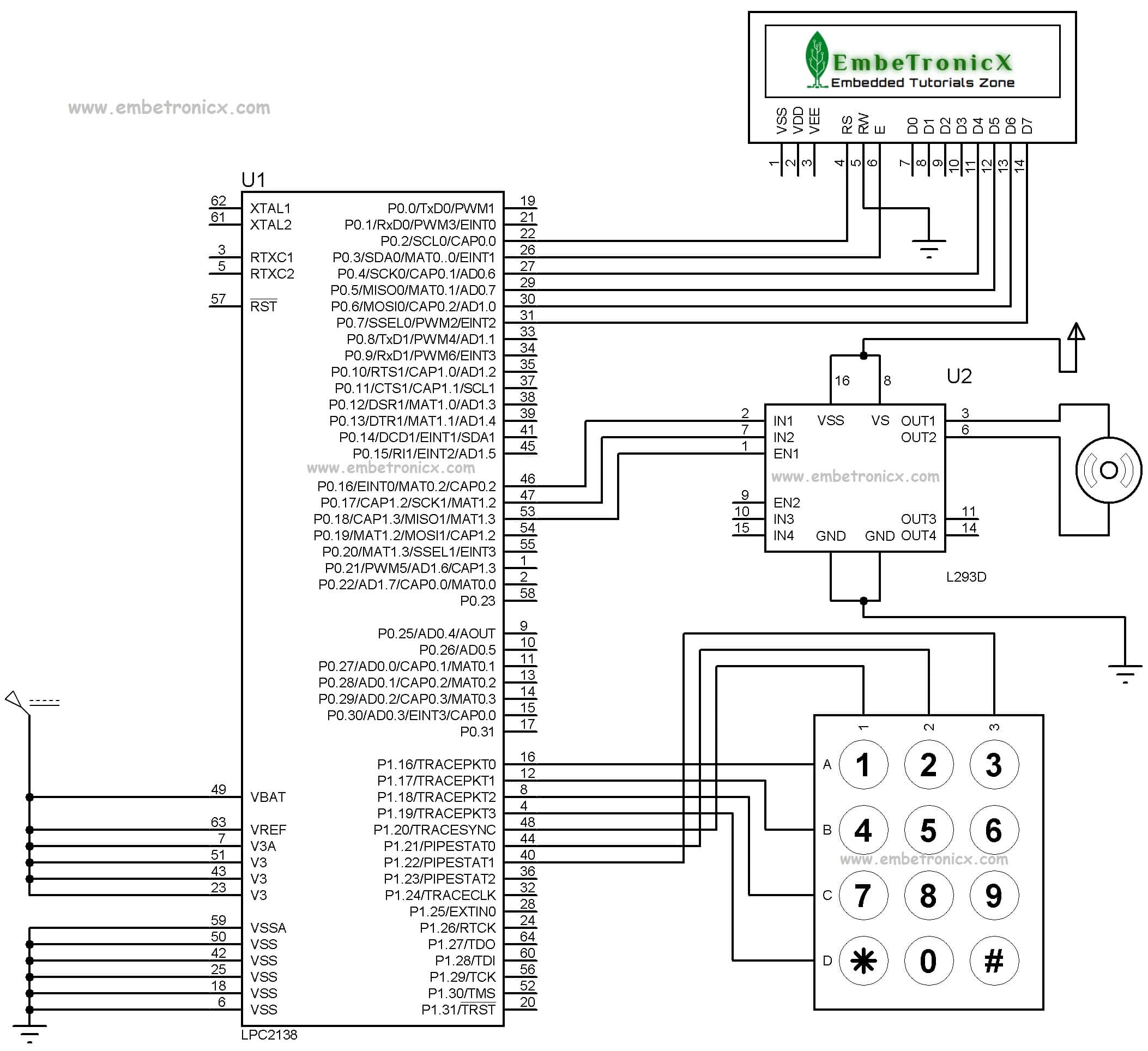
Circuit Diagram
LCD:
- RS – P0.2
- RW – GND
- EN – P0.3
- Data lines – P0.4 to P0.7 (4 Bit Mode)
DC Motor (Motor Driver):
- Input 1 – Port 0.16
- Input 2 – Port 0.17
- Enable 1 – P0.18
Keypad:
- R1 – P1.16
- R2 – P1.17
- R3 – P1.18
- R4 – P1.19
- C1 – P1.20
- C2 – P1.21
- C3 – P1.22
Code
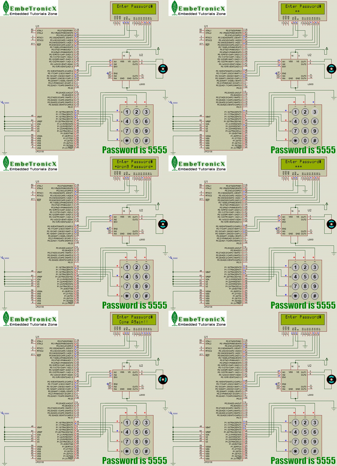
It will ask for the Password. By default password is “5555”. It will open the door and again will close if we enter the correct password. Otherwise, it won’t open the door at all.
[Download the Source code from GitHub]
#include<lpc214x.h>

#define bit(x) (1<<x)

unsigned char pass[4] = "5555";   //Set your Password

void delay ()
{
    unsigned int temp, ct;
    for(ct=0; ct<30; ct++) {
        for(temp=0; temp < 65000; temp++);
    }
}
unsigned int range=0,i;

/* --------- DC Motor ----- */
void forward(void);
void reverse(void);
void stop(void);
/* --------- LCD ---------*/

void lcd_init(void);
void cmd(unsigned char a);
void dat(unsigned char b);
void show(unsigned char *s);
void lcd_delay(void);

/* ---------- Keypad ------*/
#define c1 (IOPIN1&1<<20)
#define c2 (IOPIN1&1<<21)
#define c3 (IOPIN1&1<<22)

unsigned char r_loc,c_loc;
unsigned char key[4][3]={"123","456","789","*0#"};
unsigned char keypad(void);

/* ------- Main -------*/
int main()
{

    unsigned char rx_arr[4];
    int count;

    VPBDIV=0x01;                 // PCLK = 60MHz
    IO1DIR |= 0x0f<<16;
    IO0DIR |= 0xf00fc;

    lcd_init();

    while(1) {
        cmd(0x80);
        show("#Enter Password#");

        cmd(0xc5);
        for(count=0; count <4; count++) {
            rx_arr[count] = keypad();
            dat('*');
        }

        if ( (pass[0] == rx_arr[0]) &&
                (pass[1] == rx_arr[1]) &&
                (pass[2] == rx_arr[2]) &&
                (pass[3] == rx_arr[3]) ) {
            cmd(0xc0);
            show("   Thank You!   ");
            forward();
            delay();
            stop();
            cmd(0xc0);
            show("  Come Again!!  ");
            delay();
            reverse();
            delay();
            stop();
        } else {
            cmd(0xc0);
            show("~Wrong Password~");
            delay();
        }
        cmd(0x01);

    }
}

/* ----- Keypad Function ----*/
unsigned char keypad()
{
    IO1PIN &= ~(0xff<<16);
    IO1PIN |= 0xf0<<16;

    while(c1 && c2 && c3);
    while(!c1 || !c2 || !c3) {
        if(!c1 && c2 && c3)     c_loc=0;
        else if(c1 && !c2 && c3)    c_loc=1;
        else if(c1 && c2 && !c3)    c_loc=2;

        IO1CLR = 1<<16;
        IO1SET = 0x0e<<16;
        if(!c1 || !c2 || !c3) {
            r_loc=0;
            break;
        }

        IO1CLR = 1<<17;
        IO1SET = 0x0d<<16;
        if(!c1 || !c2 || !c3) {
            r_loc=1;
            break;
        }

        IO1CLR = 1<<18;
        IO1SET = 0x0b<<16;
        if(!c1 || !c2 || !c3) {
            r_loc=2;
            break;
        }

        IO1CLR = 1<<19;
        IO1SET = 0x07<<16;
        if(!c1 || !c2 || !c3) {
            r_loc=3;
            break;
        }
    }
    while(!c1 || !c2 || !c3);
    return (key[r_loc][c_loc]);
}


/* ----- LCD Functions -------*/

void lcd_init()
{
    cmd(0x02);
    cmd(0x28);
    cmd(0x0c);
    cmd(0x06);
    cmd(0x80);
}

void cmd(unsigned char a)
{
    IO0PIN &= 0xffffff03;
    IO0PIN |= (a & 0xf0) << 0;
    IO0CLR |= bit(2);                //rs=0
    IO0CLR |= bit(1);                //rw=0
    IO0SET |= bit(3);                 //en=1
    lcd_delay();
    IO0CLR |= bit(3);                 //en=0

    IO0PIN &= 0xffffff03;
    IO0PIN |= ((a << 4)  & 0xf0) << 0;
    IO0CLR |= bit(2);                //rs=0
    IO0CLR |= bit(1);                //rw=0
    IO0SET |= bit(3);                 //en=1
    lcd_delay();
    IO0CLR |= bit(3);                 //en=0
}

void dat(unsigned char b)
{
    IO0PIN &= 0xffffff03;
    IO0PIN |= (b & 0xf0) << 0;
    IO0SET |= bit(2);                //rs=1
    IO0CLR |= bit(1);                //rw=0
    IO0SET |= bit(3);            //en=1
    lcd_delay();
    IO0CLR |= bit(3);            //en=0

    IO0PIN &= 0xffffff03;
    IO0PIN |= ((b << 4)  & 0xf0) << 0;
    IO0SET |= bit(2);                //rs=1
    IO0CLR |= bit(1);                //rw=0
    IO0SET |= bit(3);            //en=1
    lcd_delay();
    IO0CLR |= bit(3);            //en=0
}

void show(unsigned char *s)
{
    while(*s) {
        dat(*s++);
    }
}

void lcd_delay()
    {
    unsigned int i;
    for(i=0;i<=1000;i++);
}

/* ---------- DC Motor ---------*/
void forward()
{

    IO0SET = bit(16) | bit(18);
    IO0CLR = bit(17);
}

void reverse()
{

    IO0SET = bit(17) | bit(18);
    IO0CLR = bit(16);
}

void stop()
{
    IO0CLR = bit(18);
}
Output
You can also add many features to this project like you can send messages to the owner if multiple wrong attempts, and you can add a buzzer.
You can also read the below tutorials.

Embedded Software | Firmware | Linux Devic Driver | RTOS
Hi, I am a tech blogger and an Embedded Engineer. I am always eager to learn and explore tech-related concepts. And also, I wanted to share my knowledge with everyone in a more straightforward way with easy practical examples. I strongly believe that learning by doing is more powerful than just learning by reading. I love to do experiments. If you want to help or support me on my journey, consider sharing my articles, or Buy me a Coffee! Thank you for reading my blog! Happy learning!
Share this:

Discover more from EmbeTronicX
Subscribe to get the latest posts sent to your email.
connections are made as per the circuit diagram but keypad matrix output is not showing, when keypad is pressed no change occurs, used both type of keypad, membrane and switch
connections are made but the required output is not observed, keypad matrix when pressed no changes is displayed, used both membrane and button type
i have connected as per ckt diagram given and uploaded prog sucesfully then also when im pressing keypad it is not taking input
Thanks It helped me ????????
admin is so kind and down to earth ????❤
hey bro I am done everything right but for wrong password the motor is still running please look into it again into the project
Sir , what are the peripherals and registers used in this project ?
We have used GPIO Registers.
What is the peripheral block we have used in this project, like how can we explain the peripheral block used in this project using block diagram.
We have just used the GPIO peripheral. You can get the controller’s block diagram from the internet.
Which peripheral block of ARM is used here; like UART,I2C, etc?
We have used GPIO to interface keypad, lcd and motor.
show(“#Enter Password#”);This line is showing error. WHY?
Can you print the error here? And did you modified the code?
can i get your email.i send you there
Please mail to embetronicx@gmail.com
no i didnt edit i just copy paste in keil software
Hello, As per our conversation in mail, there is no issues with the code. Issue was coming due to the keil license.
Can you please share the code of the same program with buzzer interfaced to it by today possibly at varungeographic@gmail.com. Because I am getting errors while executing the code
Hello,can I add fingerprint instead of password.can u help me about this.
Hello. can I put more Input to this program? any suggestion and solution? thanks in advance
Hello Ahmed,
You meant any input devices like switch?
yes. like push button etc.
Yes, you can do that. There are many GPIOs free. You can utilize that.
danielasraf97@gmail.com
Hi can u help? how to add buzzer if multiple wrong attempts..
Hi,
You can connect buzzer’s one end to any GPIO and another end to the ground. Then keep one variable and increment that show(“~Wrong Password~”); (line num: 77). After that, just check the variable is reached to the max. If it has reached, then make the GPIO to high where you have connected the Buzzer.