This article is a continuation of the series of tutorials on the LPC2148 Microcontroller (ARM7). The aim of this series is to provide easy and practical examples that anyone can understand. In the previous tutorial, we have interfaced the Sound detection sensor with LPC2148 (ARM7). In this tutorial, we are going to discuss Touch Sensor Interfacing with LPC2148 (TTP223B).
Table of Contents
Prerequisites
Before starting this tutorial we should know the below topics. If you know already, please go further.
Components Required
- LPC2148 Development Board
- Touch Sensor – TTP223B
- LCD Module (To print the Sensor output)
Introduction
The TTP223B is a Digital touchpad detector IC that offers 1 touch key. The touching detection IC is designed for replacing the traditional direct button key with diverse pad sizes. This device uses your body as part of the circuit.
 When you touch the sensor pad, the capacitance of the circuit is changed and is detected. That detected change in capacitance results in the output changing states. In the normal state, the module output low, low power consumption; When a finger touches the corresponding position, the module output high, if not touched for 12 seconds, switch to low-power mode.
Specification
- Operating voltage 2.0V~5.5V
- Operating current @VDD=3V, no-load, SLRFTB=1, At low power mode typical 1.5uA, maximum 3.0uA and At fast mode typical 3.5uA, maximum 7.0uA
- Operating current @VDD=3V, no-load, SLRFTB=0, At low power mode typical 2.0uA, maximum 4.0uA and At fast mode typical 6.5uA, maximum 13.0uA
- The response time max about 60mS at fast mode, 220mS at low power mode @VDD=3V
- Provides Fast mode and Low Power mode selection by pad option(LPMB pin)
- Operating Temperature:-20 ~ +70 ℃
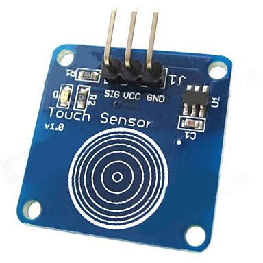
Touch Sensor Pin Outs
Like a lot of the sensors out there, this is three pin sensor. You provide power, ground, and monitor the output.
|
|
|

- SIG – Output (If it detects touch, this will be HIGH otherwise LOW)
- VCC – 2v to 5.5v
- GND – Ground
Touch Sensor Interfacing with LPC2148
Connection
Touch Sensor
- Vcc – 5v
- GND – Ground
- Sig – P1.24
LCD
- RS – P0.8
- RW – P0.9
- EN – P0.10
- Data Lines – P0.0 – P0.7

Source Code
If this sensor detects any touch, the LCD will display “Touch Detected”.
#include<lpc214x.h>
#define bit(x) (1<<x)
#define delay for(i=0;i<7000;i++);

#define TOUCH (IO1PIN & (1<<24))

unsigned int i;

void lcd_int();
void dat(unsigned char);
void cmd(unsigned char);
void string(unsigned char *);

void main()
{
    IO0DIR =0XFFF;
    IO1DIR = 0x0;
    lcd_int();
    cmd(0x80);
    string("EMBETRONICX.COM ");
    while(1) {
            if(TOUCH) {
                    string("Touch Detected");
            }
            delay;delay;
            cmd(0x01);
    }
}

void lcd_int()
{
    cmd(0x38);
    cmd(0x0c);
    cmd(0x06);
    cmd(0x01);
    cmd(0x80);
}

void cmd(unsigned char a)
{
    IO0PIN&=0x00;
    IO0PIN|=(a<<0);
    IO0CLR|=bit(8);                //rs=0
    IO0CLR|=bit(9);                //rw=0
    IO0SET|=bit(10);               //en=1
    delay;
    IO0CLR|=bit(10);               //en=0
}

void dat(unsigned char b)
{
    IO0PIN&=0x00;
    IO0PIN|=(b<<0);
    IO0SET|=bit(8);                //rs=1
    IO0CLR|=bit(9);                //rw=0
    IO0SET|=bit(10);               //en=1
    delay;
    IO0CLR|=bit(10);               //en=0
}

void string(unsigned char *p)
{
    while(*p!='\0') {
        dat(*p++);
    }
}
In our next tutorial, we will see how to interface the Flame sensor with LPC2148 (ARM7). If you want to use FreeRTOS on LPC2148, then please refer FreeRTOS series.
|
|
|
You can also read the below tutorials.
Embedded Software | Firmware | Linux Devic Deriver | RTOS
Hi, I am a tech blogger and an Embedded Engineer. I am always eager to learn and explore tech-related concepts. And also, I wanted to share my knowledge with everyone in a more straightforward way with easy practical examples. I strongly believe that learning by doing is more powerful than just learning by reading. I love to do experiments. If you want to help or support me on my journey, consider sharing my articles, or Buy me a Coffee! Thank you for reading my blog! Happy learning!
