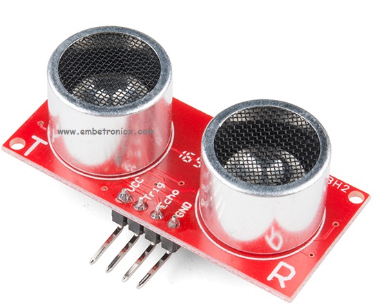
This article is a continuation of the series of tutorials on the LPC2148 Microcontroller (ARM7). The aim of this series is to provide easy and practical examples that anyone can understand. In the previous tutorial, we have interfaced the RFID reader with LPC2148 (ARM7). Now, we are going to see Ultrasonic Sensor interfacing with LPC2148.
Table of Contents
Suggestion to read
Before we will start I would suggest you to read these topics. Then you can understand this strongly. If you already know, please go ahead.
Components Required
- LPC2148 Development Board
- Ultrasonic Sensor [HC-SR04]
- LCD Module (To print the Distance)
Operation
- Connect the Trigger pin of the HC-SR04 module to any I/O pins of the LPC2148 controller and assign that Pin as an output using IODIR.
- Connect the Echo pin of the module to any I/O pins of the LPC2148 controller and assign that Pin as an input using IODIR.
- Send a pulse of minimal timer period 10us, this will make the Ultrasonic module to send a burst of data.
- Now, wait until that Echo pin goes high. Then Start the timer.
- The reflected waves will be sensed by the module and it exhibits the output in Echo pin logic low or 0.
- When the pulse from the echo pin alters its state to logic 0 or low, then stop the timer.
- The length of the pulse from the echo pin is proportional to the distance at which the object is located.
- The value in the Timer gives the distance of course with some simple calculations.
CALCULATION
According to the data sheet, the distance can be given by the formula :
|
|
|
Distance in cm = Timer /59
Distance in inch = Timer /148
Ultrasonic Sensor Interfacing with LPC2148
Connection
LCD:
- RS – P1.16
- RW – P1.17
- EN – P1.18
- Data Lines – P1.24 – P1.31
Ultrasonic Sensor:
- Trigger – P0.8
- Echo – P0.9
|
|
|
Code
Sending Trigger Pulse
void send_pulse()
{
    T0TC=T0PC=0;
    IO0SET=trig;                            //trig=1
    timer1delay(10);                        //10us delay
    IO0CLR=trig;                            //trig=0
}
Here I’m making the timer value to zero. Then we are giving high to trigger pin (1). We have to wait for 10u Seconds. So I’m using generating 10us delay using timer 1. Then make the trigger pin to low (0).
Distance Calculating
unsigned int get_range()
{
    unsigned int get=0;
    send_pulse();
    while(!echo);
    T0TCR=0x01;
    while(echo);
    T0TCR=0;
    get=T0TC;

    if(get<38000)
        get=get/59;
    else
        get=0;

    return get;
}
This is the full function to calculate the distance.
- First, I’m sending a trigger pulse.
- Then waiting until that echo pin goes high (1). Then we have to start the Timer 0.
- Again I’m waiting until that echo goes low (0). If it goes to zero, we have to stop the Timer 0.
- Then I’m taking value from the timer register.
- Then using the above formula I can calculate the Distance.
Full Code
Here I’m using Two timers. Timer 0 will be used to find the distance. And timer 1 will be used for Generating 10us Delay. Then I’m Printing the distance in LCD Module. Here PCLK will be 60MHz. You can download the full project here.
Main.c
#include<lpc214x.h>
#include"TIMER.H"
#include"ULTRASONIC.H"
#include"LCD.H"

#define delay for(i=0;i<65000;i++);

unsigned int range=0,i;

int main()
{
    VPBDIV=0x01;                 // PCLK = 60MHz
    IO1DIR=0xffffffff;
    ultrasonic_init();
    lcd_init();
    show("Distance : ");

    while(1) {
        cmd(0x8b);
        range=get_range();
        dat((range/100)+48);
        dat(((range/10)%10)+48);
        dat((range%10)+48);
        show("cm");
        delay;
        delay;
    }
}
ULTRASONIC.H
|
|
|
#define trig (1<<8)             //P0.8
#define echo (IO0PIN&(1<<9))         //P0.9 as EINT3

void ultrasonic_init();
void send_pulse();
unsigned int get_range();

void ultrasonic_init()
{
    IO0DIR|=(1<<8);
    T0CTCR=0;
    T0PR=59;
}

void send_pulse()
{
    T0TC=T0PC=0;
    IO0SET=trig;                            //trig=1
    timer1delay(10);                        //10us delay
    IO0CLR=trig;                            //trig=0
}

unsigned int get_range()
{
    unsigned int get=0;
    send_pulse();
    while(!echo);
    T0TCR=0x01;
    while(echo);
    T0TCR=0;
    get=T0TC;

    if(get<38000)
        get=get/59;
    else
        get=0;

    return get;
}
LCD.H
#define bit(x) (1<<x)

void lcd_init();
void cmd(unsigned char a);
void dat(unsigned char b);
void show(unsigned char *s);
void lcd_delay();

void lcd_init()
{
    cmd(0x38);
    cmd(0x0e);
    cmd(0x06);
    cmd(0x0c);
    cmd(0x80);
}

void cmd(unsigned char a)
{
    IO1PIN&=0x00;
    IO1PIN|=(a<<24);
    IO1CLR|=bit(16);                   //rs=0
    IO1CLR|=bit(17);                   //rw=0
    IO1SET|=bit(18);                    //en=1
    lcd_delay();
    IO1CLR|=bit(18);                    //en=0
}

void dat(unsigned char b)
{
    IO1PIN&=0x00;
    IO1PIN|=(b<<24);
    IO1SET|=bit(16);                   //rs=1
    IO1CLR|=bit(17);                   //rw=0
    IO1SET|=bit(18);               //en=1
    lcd_delay();
    IO1CLR|=bit(18);               //en=0
}

void show(unsigned char *s)
{
    while(*s) {
        dat(*s++);
    }
}

void lcd_delay()
    {
    unsigned int i;
    for(i=0;i<=1000;i++);
}
TIMER.H
void timer0delay(unsigned int a);
void timer1delay(unsigned int b);

void timer0delay(unsigned int a)    //1ms
{
    T0CTCR=0X0000;
    T0PR=59999;
    T0MR0=a;
    T0MCR=0x00000004;
    T0TCR=0X02;
    T0TCR=0X01;
    while(T0TC!=T0MR0);
    T0TC=0;
}

void timer1delay(unsigned int b)   //1us
{
    T1CTCR=0X0000;
    T1PR=59;
    T1MR0=b;
    T1MCR=0x00000004;
    T1TCR=0X02;
    T1TCR=0X01;
    while(T1TC!=T1MR0);
    T1TC=0;
}
In our next tutorial, we will see how to interface the GPS with LPC2148 (ARM7). If you want to use FreeRTOS on LPC2148, then please refer FreeRTOS series.
You can also read the below tutorials.
|
|
|

Embedded Software | Firmware | Linux Devic Deriver | RTOS
Hi, I am a tech blogger and an Embedded Engineer. I am always eager to learn and explore tech-related concepts. And also, I wanted to share my knowledge with everyone in a more straightforward way with easy practical examples. I strongly believe that learning by doing is more powerful than just learning by reading. I love to do experiments. If you want to help or support me on my journey, consider sharing my articles, or Buy me a Coffee! Thank you for reading my blog! Happy learning!


