This article is a continuation of the series of tutorials on the LPC2148 Microcontroller (ARM7). The aim of this series is to provide easy and practical examples that anyone can understand. In the previous tutorial, we have seen LPC2148 (ARM7) GPIO and LED, Switch Interfacing. Now, we will learn about LPC2148 Timer/Counter.
In the LED Interfacing program, we were used random delay, which is not precise. Now it’s time to improvise and induce precise delay using timers. Timer and counter is a very important feature which allows us to provide time variable to our microcontroller based project. Most microcontrollers come with a built-in timer peripheral.
The LPC2148 has two functionally identical general-purpose timers: Timer0 and Timer1. Both timers are 32-bit along with a 32-bit Prescaler. A timer allows us to generate precise time delays. Each Timer module can act as a Counter or Timer.
Table of Contents
Suggestion to read
LPC2148 Timer Features
- A 32-bit Timer/Counter with a programmable 32-bit Prescaler.
- Counter or Timer operation
- Up to four 32-bit capture channels per timer, that can take a snapshot of the timer value when an input signal transitions. A capture event may also optionally generate an interrupt.
- Four 32-bit match registers that allow:
- Continuous operation with optional interrupt generation on match.
- Stop timer on match with optional interrupt generation.
- Reset timer on match with optional interrupt generation.
- Up to four external outputs corresponding to match registers, with the following capabilities:
- Set low on the match.
- Set high on the match.
- Toggle on match.
- Do nothing on match.
There are some registers used for Configuring and Running the Timer. Before getting into Registers, first, we will see the working of Timer in LPC2148.
LPC2148 Timer Working Operation
The Timer/Counter is designed to count cycles of the peripheral clock (PCLK) or an externally supplied clock, and can optionally generate interrupts or perform other actions at specified timer values, based on four match registers.
|
|
|
The heart of timers of the LPC2148 Microcontroller is a 32-bit free-running counter, which is designed to count cycles of the Peripheral Clock (PCLK) or an external clock, this counter is programmable with a 32-bit Prescaler.
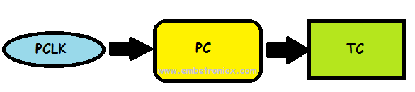
The tick rate of the Timer Counter (TC) is controlled by the 32-bit number written in the Prescaler Register (PR) in the following way. There is a Prescale Counter (PC) that increments on each tick of the PCLK. When it reaches the value in the Prescaler register, the timer count is incremented and the Prescaler Counter (PC) is reset, on the next PCLK. This causes the timer counters to increment on every PCLK when PR=0, every 2 PCLKs when PR=1, etc.
Now we will look into the Registers used in Timers/Counters.
Registers Used in LPC2148 Timer
The below table shows the registers associated with the LPC2148 Timer module. In this tutorial, we will concentrate only on the Timer module. We will post the Capture register soon.
|
|
|
| Register | Description |
|---|---|
| IR | Interrupt Register: The IR can be read to identify which of 6(4-match, 2-Capture) possible interrupt sources are pending. Writing Logic-1 will clear the corresponding interrupt. |
| TCR | Timer Control Register: The TCR is used to control the Timer Counter functions(enable/disable/reset). |
| TC | Timer Counter: The 32-bit TC is incremented every PR+1 cycles of PCLK. The TC is controlled through the TCR. |
| PR | Prescaler Register: This is used to specify the Prescaler value for incrementing the TC. |
| PC | Prescale Counter: The 32-bit PC is a counter which is incremented to the value stored in PR. When the value in PR is reached, the TC is incremented. |
| CTCR | Count Control Register. The CTCR selects between Timer and Counter mode, and in Counter mode selects the signal and edge(s) for counting. |
| MR0-MR3 | Match Registers: The Match register values are continuously compared to the Timer Counter value. When the two values are equal, actions can be triggered automatically. The action possibilities are to generate an interrupt, reset the Timer Counter, or stop the timer. Actions are controlled by the settings in the MCR register. |
| MCR | Match Control Register: The MCR is used to control the resetting of TC and generating of interrupt whenever a Match occurs. |
| CR0 - CR4 | Capture Registers. TC value is loaded to this Capture Register when there is an event on the CAPn.0 - CAPn.4 |
| CCR | Capture Control Register. The CCR controls which edges of the capture inputs are used to load the Capture Registers and whether or not an interrupt is generated when a capture takes place. |
Interrupt Register (IR)
Interrupt Register consists of flag bits for Match Interrupts and Capture Interrupts. It contains four bits each for match and capture interrupts. Bits 0 to 3 in the IR register are for Match Register Interrupts i.e. Bit 0 for MR0 interrupt, Bit 1 for MR1 interrupt, etc. Bits 4 to 7 are for Capture Register Interrupts Bit 4 for CR0 interrupt, Bit 5 for CR1 interrupts, etc. If an interrupt is triggered, then the corresponding bit in the IR register is set to 1. Manually writing a logic 1 on the bit of the IR register will reset the interrupt. Writing a zero has no effect.

Timer Control Register (TCR)
Timer Control Register is used to control the functions of the timer/counter. It is used to enable/disable or reset the Timer Counter. Timer Control Register is used to control the functions of the timer/counter. It is used to enable/disable or reset the Timer Counter. When the first bit (TSR [0]) is 0, Timer Counter and Prescale Counter are disabled. When the first bit is 1, the counters are enabled. When the second bit (TSR [1]) is 1, both the counters (Timer Counter and Prescale Counter) are reset on the next positive edge of the peripheral clock. They remain reset until the second bit is set to 0.

Count Control Register (CTCR)
Count Control Register is used to set either Timer mode or Counter Mode. If Counter Mode is selected, the counter pin and the edges (rising, falling, or both) can be selected using CTCR. In this tutorial, we are going to use only the Timer Mode and hence CTCR is set to “0x0”.
|
|
|
Timer Counter Register (TC)
The value in the Timer Counter register in incremented when the value PC reaches its terminal value as set by the PR register. If the PC is reset before reaching its maximum value, then the TC will count to the maximum possible value i.e. 0xFFFF FFFF (since it is a 32 – bit register) and resets back to 0x0000 0000. This event does not cause an interrupt, but a Match register can be used to detect an overflow if needed.
Prescale Register (PR)
Prescale Register specifies the maximum value for the Prescale Counter. When the Prescale Counter (PC) is equal to PR, the TC is incremented on the next clock and also PC is cleared.
Prescale Counter Register (PC)
Prescale Counter increments on every peripheral clock to the value stored in the PR. When the value in the PC is equal to the value in the PR, the PC is reset and TC is incremented by 1 on the next clock cycle. For example, if PR = 2, then TC is incremented on every third cycle of the peripheral clock. Hence, PC defines the resolution of the Timer.
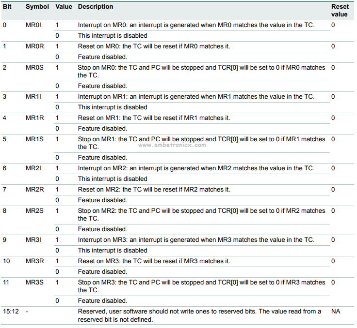
Match Control Register (MCR)
The Match Control Register is used to control the actions to be performed when the value in the Match Register (MR) matches with the value in the Timer Counter (TC). Bits 0 to 2 in MCR (i.e. MCR [0], MCR [1] and MCR [2]) are used to control the actions for MR0 register. Similarly, bits 3 to 5 for MR1, bits 6 to 8 for MR2, and bits 9 to 11 for MR3 respectively. We will see the function associated with MR0.
-
Bit 0: When this bit is 1, an interrupt is triggered when MR0 is equal to TC. When this bit is 0, the interrupts are disabled.
-
Bit 1: When this bit is 1, TC is reset when MR0 is equal to TC. When this bit is 0, this feature is disabled.
-
Bit 2: When this bit is 1, the Timer Counter (TC) and Prescale Counter (PC) are stopped when the value in MR0 is equal to TC. Also, the TC is reset to 0.
Similar actions can be applicable for other Match Register.
Match Registers (MR0 – MR3)
The Match register values are continuously compared to the Timer Counter value. When the two values are equal, actions can be triggered automatically. The action possibilities are to generate an interrupt, reset the Timer Counter, or stop the timer. Actions are controlled by the settings in the MCR register.
|
|
|
Capture Control Registers (CCR)
The Capture Control Register is used to control whether one of the four Capture Registers is loaded with the value in the Timer Counter when the capture event occurs and whether an interrupt is generated by the capture event.
Capture Registers (CR0 -CR3)
Each Capture register is associated with a device pin and may be loaded with the Timer Counter value when a specified event occurs on that pin. The settings in the Capture Control Register determine whether the capture function is enabled and whether a capture event happens on the rising edge of the associated pin, the falling edge, or on both edges.
Configuring Timer
To use timers we need to first configure them. I would like to encourage the readers to use the following sequence for Setting up Timers:
-
Set appropriate value in TxCTCR
-
Define the Prescale value in TxPR
-
Set Value(s) in Match Register(s) if required
-
Set appropriate value in TxMCR if using Match registers / Interrupts
-
Reset Timer – Which resets PR and TC
-
Set TxTCR to 0x01 to Enable the Timer when required
-
Reset TxTCR to 0x00 to Disable the Timer when required
Prescale Register Value Calculation
The delay or time required for 1 clock cycle at ‘X’ MHz is given by :
Delay = 1/(X*1000000) Seconds
Hence in our case when PR=0 i.e TC increments at every PCLK the delay required for TC to increment by 1 is:
Delay = (0+1)/(60*1000000) Seconds
Similarly, when we set PR = 59999 the delay will be:
|
|
|
Delay = (599999+1)/(60*1000000) Seconds
Delay = 1mS
… which boils down to 1/1000 = 0.001 Seconds which is nothing but 1 Milli-Second i.e mS. Hence the delay required for TC to increment by 1 will be 1mS.
Code
Without Match Register
In this code LED will Blink with a 1-second delay. I’m using Timer 0 in this code. LEDs are connected to Port 0. Here My PCLK is 60MHz. You can download the entire project here.
#include<lpc214x.h>

void delay(unsigned int z);

void pll();

int main(void)
{
    IO0DIR=0xffffffff;
    pll();                  //Fosc=12Mhz,CCLK=60Mhz,PCLK=60MHz
    while(1) {
        IO0SET=0xffffffff;
        delay(1000);               //1sec delay
        IO0CLR=0xffffffff;
        delay(1000);               //1sec delay
    }
}


void pll()                  //Fosc=12Mhz,CCLK=60Mhz,PCLK=60MHz
{
    PLL0CON=0x01;
    PLL0CFG=0x24;
    PLL0FEED=0xaa;
    PLL0FEED=0x55;
    while(!(PLL0STAT&(1<<10)));
    PLL0CON=0x03;
    PLL0FEED=0xaa;
    PLL0FEED=0x55;
    VPBDIV=0x01;
}


void delay(unsigned int z)
{
    T0CTCR=0x0;                                 //Select Timer Mode
    T0TCR=0x00;                 //Timer off
    T0PR=59999;                 //Prescaler value for 1ms
    T0TCR=0x02;                 //Timer reset
    T0TCR=0x01;                 //Timer ON
    while(T0TC<z);
    T0TCR=0x00;                 //Timer OFF
    T0TC=0;                     //Clear the TC value. This is Optional.
}
With Match Register
In this code LED will Blink with a 1-second delay. I’m using Timer 1 in this code. LEDs are connected to Port 0. Here My PCLK is 60MHz. You can download the entire project here.
|
|
|
#include<lpc214x.h>

void pll()                       //Fosc=12Mhz,CCLK=60Mhz,PCLK=60MHz
{
    PLL0CON=0X01;
    PLL0CFG=0X24;
    PLL0FEED=0XAA;
    PLL0FEED=0X55;
    while((PLL0STAT&(1<<10))==0);
    PLL0CON=0X03;
    PLL0FEED=0XAA;
    PLL0FEED=0X55;
    VPBDIV=0X01;
}

void wait()
{
    T1CTCR=0X0000;          //Timer Mode
    T1PR=59999;                 //Prescaler Value
    T1MR0=1000;                 //Match Register Value
    T1MCR=0x00000004;       //TC and PC will be stopped and TCR[0] will be set to 0 if MR0 matches the TC.
    T1TCR=0X02;                 //Reset Timer
    T1TCR=0X01;                 //Timer ON
    while(T1TC!=T1MR0);
    T1TC=0;                         //Timer OFF
}

int main(void)
{

    IO0DIR=0xffffffff;
    pll();                             //Fosc=12Mhz,CCLK=60Mhz,PCLK=60MHz

    while(1) {
        IO0SET=0xffffffff;
        wait();
        IO0CLR=0xffffffff;
        wait();
    }

}
In our next tutorial, we will see LPC2148 (ARM7) UART. If you want to use FreeRTOS on LPC2148, then please refer FreeRTOS series.
You can also read the below tutorials.
Embedded Software | Firmware | Linux Devic Deriver | RTOS
Hi, I am a tech blogger and an Embedded Engineer. I am always eager to learn and explore tech-related concepts. And also, I wanted to share my knowledge with everyone in a more straightforward way with easy practical examples. I strongly believe that learning by doing is more powerful than just learning by reading. I love to do experiments. If you want to help or support me on my journey, consider sharing my articles, or Buy me a Coffee! Thank you for reading my blog! Happy learning!
