Hi all… In our previous tutorials, we have seen Relay interfacing with 8051. Today we will see 8051 Keypad Interfacing. Before that, I would suggest you to go through this link to know about the Keypad characteristics. And I assumed that you know LCD interfacing. Otherwise, you can see that LCD interfacing tutorials on our website. Let’s start…
Table of Contents
8051 Keypad Interfacing
Components Required
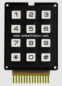
- 4×4 Keypad or 3×4 Keypad (Here we will discuss both codes)
- LCD Module (To print the Keys pressed)
- 8051 Microcontroller
4×4 Matrix Keypad Interfacing
Circuit Diagram

LCD
- RS – P3.5
- RW – P3.6
- EN – P3.7
- Data Lines – P2
Keypad
- R1 – P1.0
- R2 – P1.1
- R3 – P1.2
- R4 – P1.3
- C1 – P1.4
- C2 – P1.5
- C3 – P1.6
- C4 – P1.7
Code
This code might be looking big. But concept-wise it is very easy. Please go through this code.
|
|
|
#include<reg51.h>

#define lcd P2

sbit rs=P3^5;
sbit rw=P3^6;
sbit en=P3^7;

sbit r1=P1^0;
sbit r2=P1^1;
sbit r3=P1^2;
sbit r4=P1^3;
sbit c1=P1^4;
sbit c2=P1^5;
sbit c3=P1^6;
sbit c4=P1^7;


void lcd_init();
void cmd(unsigned char );
void dat(unsigned char );
lcd_string(unsigned char *);
void delay(unsigned int );
void keypad(void);


void main()
{
    lcd_init();
    while(1) {
        cmd(0x80);
        lcd_string("Enter the key:");
        cmd(0xc7);
        keypad();
    }
}

void keypad()
{
    c1=c2=c3=c4=1;
    r1=0;r2=1;r3=1;r4=1;
    if(c1==0){
        while(c1==0);
        dat('7');
    } else if(c2==0) {
        while(c2==0);
        dat('8');
    } else if(c3==0) {
        while(c3==0);
        dat('9');
    } else if(c4==0) {
        while(c4==0);
        dat('/');
    }

    r1=1;r2=0;r3=1;r4=1;
    if(c1==0){
        while(c1==0);
        dat('4');
    } else if(c2==0) {
        while(c2==0);
        dat('5');
    } else if(c3==0) {
        while(c3==0);
        dat('6');
    } else if(c4==0) {
        while(c4==0);
        dat('*');
    }

    r1=1;r2=1;r3=0;r4=1;
    if(c1==0){
        while(c1==0);
        dat('1');
    } else if(c2==0) {
        while(c2==0);
        dat('2');
    } else if(c3==0) {
        while(c3==0);
        dat('3');
    } else if(c4==0) {
        while(c4==0);
        dat('-');
    }

    r1=1;r2=1;r3=1;r4=0;
    if(c1==0){
        while(c1==0);
        cmd(0x01);
    } else if(c2==0) {
        while(c2==0);
        dat('0');
    } else if(c3==0) {
        while(c3==0);
        dat('=');
    } else if(c4==0) {
        while(c4==0);
        dat('+');
    }
}


void lcd_init()
{
        cmd(0x38);
        cmd(0x0e);
        cmd(0x06);
        cmd(0x01);
}

void cmd(unsigned char x)
{
        lcd=x;
        rs=0;
        rw=0;
        en=1;
        delay(1000);
        en=0;
}

void dat(unsigned char y)
{
        lcd=y;
        rs=1;
        rw=0;
        en=1;
        delay(1000);
        en=0;
}

lcd_string(unsigned char *s)
{
    while(*s)
        dat(*s++);
}

void delay(unsigned int z)
{
  unsigned int i;
  for(i=0;i<=z;i++);
}
Code Explanation
I assumed that you already know about LCD interfacing. Now look at these lines in keypad function,
      c1=c2=c3=c4=1;
    r1=0;r2=1;r3=1;r4=1;
    if(c1==0){
        while(c1==0);
        dat('7');
    } else if(c2==0) {
        while(c2==0);
        dat('8');
    } else if(c3==0) {
        while(c3==0);
        dat('9');
    } else if(c4==0) {
        while(c4==0);
        dat('/');
    }
In this code, I’m taking row as output and column as input.
- In the first line, I’m assigning high to all columns. (c1=c2=c3=c4=1;)
- Then I’m assigning the first row to zero and keeps the remaining row as high. (r1=0;r2=1;r3=1;r4=1;)
- Then I’m checking the first column is zero or not. If it is zero then I should wait until that button depressed. Then I can know the pressed key.
- If not I’m checking the next column. Like that, I’m checking all rows and columns.
- If no keys pressed in row1, then I’m making row2 as zero. The remaining rows are high. Then follow the above steps.
Output
Check the below output.
3×4 Matrix Keypad Interfacing
Circuit Diagram

|
|
|
LCD
- RS – P3.5
- RW – P3.6
- EN – P3.7
- Data Lines – P2
Keypad
- R1 – P1.0
- R2 – P1.1
- R3 – P1.2
- R4 – P1.3
- C1 – P1.4
- C2 – P1.5
- C3 – P1.6
Code
#include<reg51.h>

#define lcd P2

sbit rs=P3^5;
sbit rw=P3^6;
sbit en=P3^7;

sbit r1=P1^0;
sbit r2=P1^1;
sbit r3=P1^2;
sbit r4=P1^3;
sbit c1=P1^4;
sbit c2=P1^5;
sbit c3=P1^6;


void lcd_init();
void cmd(unsigned char );
void dat(unsigned char );
lcd_string(unsigned char *);
void delay(unsigned int );
void keypad(void);


void main()
{
    lcd_init();
    while(1) {
        cmd(0x80);
        lcd_string("Enter the key:");
        cmd(0xc7);
        keypad();
    }
}

void keypad()
{
    c1=c2=c3=1;
    r1=0;r2=1;r3=1;r4=1;
    if(c1==0){
        while(c1==0);
        dat('1');
    } else if(c2==0) {
        while(c2==0);
        dat('2');
    } else if(c3==0) {
        while(c3==0);
        dat('3');
    }

    r1=1;r2=0;r3=1;r4=1;
    if(c1==0){
        while(c1==0);
        dat('4');
    } else if(c2==0) {
        while(c2==0);
        dat('5');
    } else if(c3==0) {
        while(c3==0);
        dat('6');
    }

    r1=1;r2=1;r3=0;r4=1;
    if(c1==0){
        while(c1==0);
        dat('7');
    } else if(c2==0) {
        while(c2==0);
        dat('8');
    } else if(c3==0) {
        while(c3==0);
        dat('9');
    }

    r1=1;r2=1;r3=1;r4=0;
    if(c1==0){
        while(c1==0);
        dat('*');
    } else if(c2==0) {
        while(c2==0);
        dat('0');
    } else if(c3==0) {
        while(c3==0);
        dat('#');
    }
}


void lcd_init()
{
        cmd(0x38);
        cmd(0x0e);
        cmd(0x06);
        cmd(0x01);
}

void cmd(unsigned char x)
{
        lcd=x;
        rs=0;
        rw=0;
        en=1;
        delay(1000);
        en=0;
}

void dat(unsigned char y)
{
        lcd=y;
        rs=1;
        rw=0;
        en=1;
        delay(1000);
        en=0;
}

lcd_string(unsigned char *s)
{
    while(*s)
        dat(*s++);
}

void delay(unsigned int z)
{
  unsigned int i;
  for(i=0;i<=z;i++);
}
Code Explanation
Same as the 4×4 Matrix keypad.
Output
 [ Please find the output image Here ]
Tasks
Please try these tasks. If you have any doubt please ask us by commenting below.
|
|
|
- Whatever I’m pressing in the Keypad that character should be displayed in the Serial terminal.
- Connect 8 LEDs into Port 0. If I press 0, No LEDs will be ON. If I press 1, 1 LED should be ON. If I press 2, 2 LEDs should ON. Like that up to 8 numbers, you write the program.
In our next tutorial, we will discuss the ADC0804 interfacing with 8051.
You can also read the below tutorials.
Embedded Software | Firmware | Linux Devic Deriver | RTOS
Hi, I am a tech blogger and an Embedded Engineer. I am always eager to learn and explore tech-related concepts. And also, I wanted to share my knowledge with everyone in a more straightforward way with easy practical examples. I strongly believe that learning by doing is more powerful than just learning by reading. I love to do experiments. If you want to help or support me on my journey, consider sharing my articles, or Buy me a Coffee! Thank you for reading my blog! Happy learning!
