Bluetooth is one of the most popular wireless protocols, and it has been available in smartphones, computers, and other devices for over a decade. Most of us are familiar with Bluetooth and how Bluetooth can allow us to connect a headset and make calls using our cell phones. The explosive growth in Bluetooth devices led the Bluetooth SIG and other companies to the realization that Bluetooth consumed too much power and took too long to connect in some applications. So that they have implemented Bluetooth Low Energy, mostly called as BLE. So now we will see the Bluetooth Low Energy Basics (BLE Basics). I’ve divided this tutorial into two parts. In this Part 1, we will see the very basic things about BLE.
You can also read BLE Part-2, I2C basics, Bluetooth interfacing with LPC2148, Bluetooth interfacing with PIC16F877A, and Bluetooth interfacing with 8051
Table of Contents
Bluetooth Low Energy Basics
Bluetooth Low Energy (BLE) Introduction
Bluetooth Low Energy is also called as BLE and Bluetooth Smart. When Bluetooth released the Bluetooth 4.0 core specification, they introduced BLE. The BLE was actually started by Nokia, as a project once called “Wibree”, and was introduced in 2006 under that certain name. In 2010, the Bluetooth Special Interest Group merged Wibree into the Bluetooth standard as a part of the 4.0 core specification. Although it is a part of the same specification, BLE alone is not backward compatible with Bluetooth, and so we can not treat it as the same protocol like Bluetooth.
Nowadays everyone is having a mobile phone. So, BLE can communicate with a large number of mobile devices find today, phones which run Android, OS X, Windows Phone, iOS, and BlackBerry, as well as Linux, and Windows 8 all support BLE. This means that you can integrate your project easy to make a multi-platformed communication. The main big advantage of the BLE is it consumes very very little power. BLE, unlike the classic Bluetooth standard, is designed to reduce power consumption, allowing your BLE device to run for months or years on a coin-cell battery. Now let’s learn the working of BLE.
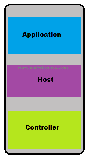
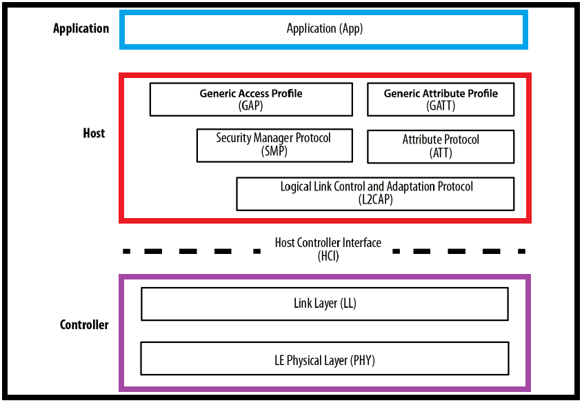
Building Blocks of Bluetooth Device
There are three main building blocks in every Bluetooth device.
-
Application
-
Host
-
Controller
Application
The user application interfacing with the Bluetooth protocol stack to cover a particular use case.
Host
The upper layers of the Bluetooth protocol stack.
Controller
The lower layers of the Bluetooth protocol stack, including the radio.
Additionally, the specification provides a standard communications protocol between the host and the controller. That is Host Controller Interface (HCI). It is used to allow interoperability between hosts and controllers produced by different companies.
These layers can be implemented in a single integrated circuit (IC) or chip, or they can be split into several ICs connected through a communication layer (UART, USB, SPI, or other).
Data Throughput
The modulation rate of the Bluetooth Low Energy radio is set by the specification at a constant 1Mbps. This, of course, is the theoretical upper limit. In practice, you can expect between 5-10 KB per second, depending on the limitations of the devices used.
Operating Range
The actual range of any wireless device depends on a wide variety of factors (operating environment, antenna design, enclosure, device orientation, etc.) but Bluetooth Low Energy is unsurprisingly focused on very short-range communication. It’s possible to create and configure a BLE device that can reliably transmit data 30 meters or more line-of-sight, but a typical operating range is probably closer to 2 to 5 meters. Of course, the higher the range the more battery consumption, so take care when trying to tweak your device for a higher range.
Network Topology
A Bluetooth Low Energy device can communicate with the outside world in two ways:
-
Broadcasting
-
Connections
Broadcasting
Well. Have you heard about the term Broadcasting? What is it? Exactly. Broadcasting means sending data to more than one member. Same here also. Broadcasting is the act of sending data out to all the listening devices. Using connection-less broadcasting, you can send data out to any scanning device or receiver in the listening range. See the below picture.
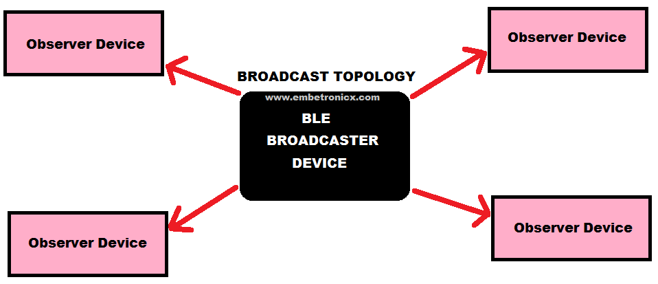
This mechanism essentially allows you to send data out one-way to anyone or anything that is capable of picking up the transmitted data.
Broadcasting defines two parts.
-
Broadcaster
-
Observer
Broadcaster
Sends non-connectable advertising packets periodically to anyone willing to receive them.
Observer
Repeatedly scans the preset frequencies to receive any non connectable advertising packets currently being broadcasted.
Each advertising packet can carry up to 31 bytes of advertising data payload, along with the basic header information (including Bluetooth device address). Such packets are simply broadcast blindly over the air by the advertiser without the previous knowledge of the presence of any scanning device.
Broadcasting is fast and easy to use, and it’s a good choice if you want to push only a small amount of data on a fixed schedule or to multiple devices.
Note: A major limitation of broadcasting, when compared to a regular connection, is that there are no security or privacy provisions at all with it (any observer device is able to receive the data being broadcasted), so it might not be suited for sensitive data.
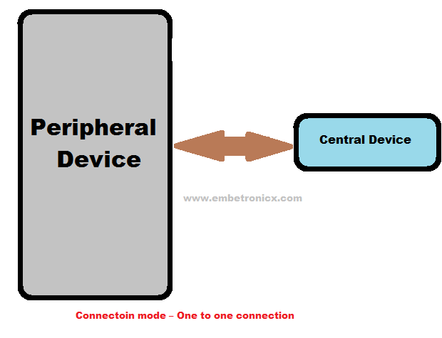
Connections
If you need to transmit data in both directions, or if you have more data than the two advertising payloads can accommodate, you will need to use a connection. A connection is a permanent, periodical data exchange of packets between two devices.
Connections involve two separate roles:
-
Central/Master
-
Peripherals/Slave
Central/Master
Central devices are usually mobile phones or PCs which have a higher CPU processing power. This Central device repeatedly scans the particular frequencies for advertising packets. If it finds any suitable packets, it will initiate the connection. Once the connection is established, the central manages the timing and initiates the periodical data exchanges.
Peripherals/Slave
Peripheral devices are usually some sensors or low-power devices, which connect to the central device. So this peripheral device sends the advertising packets periodically. And also it accepts the incoming connection. Once in an active connection, the peripheral follows the central’s timing and exchanges data regularly with it.
I explained the connection procedure below.
-
Peripheral devices periodically send the advertising packets.
-
Central devices scanning the advertising packets from nearby peripheral devices.
-
If the central device finds a suitable advertising packet, It sends the connection requests to the peripheral device.
-
Peripheral devices accept the incoming connection.
-
After establishing the connection, the Peripheral device stops the advertising and follows the central device.
-
Now two devices can exchange the data in two directions.
Beginning with version 4.1 of the specification, any restrictions on role combinations have been removed, and the following are all possible:
-
A device can act as a central and a peripheral at the same time.
-
A central can be connected to multiple peripherals.
-
A peripheral can be connected to multiple central.
In the below diagram, I have explained both advertising and connection modes.

These all the very basics of Bluetooth Low Energy (BLE). Now we will go into some depth. Let’s start the Bluetooth Low Energy (BLE) Protocol Stack.
BLE Protocol Stack
BLE, like many other wireless technologies, is organized in a number of layers. Each layer has its purpose and plays a significant role in making a BLE device function properly. As we discussed before there are three building blocks present in the BLE.
-
Application
-
Host
-
Controller
Each of these basic building blocks of the protocol stack is split into several layers that provide the functionality required to operate:
Application
The application, like in all other types of systems, is the highest layer and the one responsible for containing the logic, user interface, and data handling of everything related to the actual use-case that the application implements. The architecture of an application is highly dependent on each particular implementation.
Host
The host contains the following layers.
-
Generic Access Profile (GAP)
-
Generic Attribute Profile (GATT)
-
Logical Link Control and Adaptation Protocol (L2CAP)
-
Attribute Protocol (ATT)
-
Security Manager (SM)
-
Host Controller Interface (HCI), the Host side
Controller
The controller contains the following layers.
-
Host Controller Interface (HCI), Controller side
-
Link Layer (LL)
-
Physical Layer (PHY)
Now that we know a bit about Bluetooth Low Energy Basics. In our next part (Part 2) we will see the whole protocol stacks layers of BLE. I hope you would enjoy this tutorial. Let’s breathe freely 😆
You can also read the below tutorials.
Embedded Software | Firmware | Linux Devic Deriver | RTOS
Hi, I am a tech blogger and an Embedded Engineer. I am always eager to learn and explore tech-related concepts. And also, I wanted to share my knowledge with everyone in a more straightforward way with easy practical examples. I strongly believe that learning by doing is more powerful than just learning by reading. I love to do experiments. If you want to help or support me on my journey, consider sharing my articles, or Buy me a Coffee! Thank you for reading my blog! Happy learning!
