This article is a continuation of the series of tutorials on the PIC16F877A Microcontroller. The aim of this series is to provide easy and practical examples that anyone can understand. In the previous tutorial, we have interfaced the Relay with PIC16F877A. In this tutorial, we will learn Keypad Interfacing with PIC16F877A.
Table of Contents
Prerequisites
Components Required
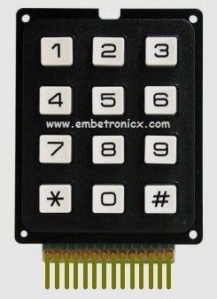
- 4×4 Keypad
- PIC16F877A Microcontroller
Keypad Interfacing with PIC16F877A
Circuit Diagram
LCD:
- RS – Port D.2
- RW – GND
- EN – Port D.3
- Data Lines – Port D.4 – Port D.7
Keypad:
- Row1 – RB0
- Row2 – RB1
- Row3 – RB2
- Row4 – RB3
- Col1 – RB4
- Col2 – RB5
- Col3 – RB6
- Col4 – RB7

Code
You can download the full project Here.
|
|
|
#include <pic.h>

__CONFIG( FOSC_HS & WDTE_OFF & PWRTE_OFF & CP_OFF & BOREN_ON & LVP_OFF & CPD_OFF & WRT_OFF & DEBUG_OFF);


#define rs RD2
#define en RD3

#define R1 RB0
#define R2 RB1
#define R3 RB2
#define R4 RB3
#define C1 RB4
#define C2 RB5
#define C3 RB6
#define C4 RB7

void lcd_init();
void cmd(unsigned char a);
void dat(unsigned char b);
void show(unsigned char *s);
void lcd_delay();

unsigned char key();
void keyinit();

unsigned char keypad[4][4]={{'7','8','9','/'},{'4','5','6','*'},{'1','2','3','-'},{'C','0','=','+'}};
unsigned char rowloc,colloc;

void main()
{
    unsigned int i;
    TRISD=0;
    lcd_init();
    keyinit();
    unsigned char b;
    cmd(0x80);
    show("  Enter the Key ");
    while(1)
    {
        cmd(0xc7);
        b=key();
        dat(b);

    }
}

void lcd_init()
{
    cmd(0x02);
    cmd(0x28);
    cmd(0x0e);
    cmd(0x06);
    cmd(0x80);
}

void cmd(unsigned char a)
{
    rs=0;
    PORTD&=0x0F;
    PORTD|=(a&0xf0);
    en=1;
    lcd_delay();
    en=0;
    lcd_delay();
    PORTD&=0x0f;
    PORTD|=(a<<4&0xf0);
    en=1;
    lcd_delay();
    en=0;
    lcd_delay();
}

void dat(unsigned char b)
{
    rs=1;
    PORTD&=0x0F;
    PORTD|=(b&0xf0);
    en=1;
    lcd_delay();
    en=0;
    lcd_delay();
    PORTD&=0x0f;
    PORTD|=(b<<4&0xf0);
    en=1;
    lcd_delay();
    en=0;
    lcd_delay();
}

void show(unsigned char *s)
{
    while(*s) {
        dat(*s++);
    }
}

void lcd_delay()
{
    unsigned int lcd_delay;
    for(lcd_delay=0;lcd_delay<=1000;lcd_delay++);
}

void keyinit()
{
    TRISB=0XF0;
    OPTION_REG&=0X7F;           //ENABLE PULL UP
}

unsigned char key()
{
    PORTB=0X00;
    while(C1&&C2&&C3&&C4);
    while(!C1||!C2||!C3||!C4) {
        R1=0;
        R2=R3=R4=1;
        if(!C1||!C2||!C3||!C4) {
            rowloc=0;
            break;
        }
        R2=0;R1=1;
        if(!C1||!C2||!C3||!C4) {
            rowloc=1;
            break;
        }
        R3=0;R2=1;
        if(!C1||!C2||!C3||!C4) {
            rowloc=2;
            break;
        }
        R4=0; R3=1;
        if(!C1||!C2||!C3||!C4){
            rowloc=3;
            break;
        }
    }
    if(C1==0&&C2!=0&&C3!=0&&C4!=0)
            colloc=0;
    else if(C1!=0&&C2==0&&C3!=0&&C4!=0)
            colloc=1;
    else if(C1!=0&&C2!=0&&C3==0&&C4!=0)
            colloc=2;
    else if(C1!=0&&C2!=0&&C3!=0&&C4==0)
            colloc=3;
    while(C1==0||C2==0||C3==0||C4==0);
    return (keypad[rowloc][colloc]);
}
Output
Whatever we are typing in the keypad, it will display that character in LCD Module.
 [ Please find the output image Here ]
In our next tutorial, we will see how to interface the GSM module with PIC16F877A.
You can also read the below tutorials.
|
|
|
Embedded Software | Firmware | Linux Devic Deriver | RTOS
Hi, I am a tech blogger and an Embedded Engineer. I am always eager to learn and explore tech-related concepts. And also, I wanted to share my knowledge with everyone in a more straightforward way with easy practical examples. I strongly believe that learning by doing is more powerful than just learning by reading. I love to do experiments. If you want to help or support me on my journey, consider sharing my articles, or Buy me a Coffee! Thank you for reading my blog! Happy learning!
