This article is a continuation of the series of tutorials on the PIC16F877A Microcontroller. The aim of this series is to provide easy and practical examples that anyone can understand. In our previous tutorial, we have seen how to use multiple external interrupts in PIC16F877A.
In this tutorial, we will learn LCD Interfacing with PIC16F877A with circuit and code.
Table of Contents
LCD Interfacing with PIC16F877A
16×2 LCD
We always use devices made up of Liquid Crystal Displays (LCDs) like computers, digital watches, and also DVD and CD players. They have become very common and have taken a giant leap in the screen industry by clearly replacing the use of Cathode Ray Tubes (CRT).
CRT draws more power than LCD and is also bigger and heavier. All of us have seen an LCD, but no one knows the exact working of it.
Let us have a look at the working of an LCD. Here we are using an alphanumeric LCD 16×2.
|
|
|
A 16×2 LCD is a very basic module and is very commonly used in various devices and circuits. These modules are preferred over seven segments and other multi-segment LEDs.
The reasons are that LCDs are economical; easily programmable; and have no limitation of displaying special & even custom characters (unlike in seven segments), animations, and so on.
A 16×2 LCD means it can display 16 characters per line, and there are 2 such lines. In this LCD, each character is displayed in a 5×7 pixel matrix.
This LCD has two registers, namely, Command and Data.
The command register stores the command instructions given to the LCD. A command is an instruction given to LCD to do a predefined task like initializing it, clearing its screen, setting the cursor position, controlling the display, etc.
|
|
|
The data register stores the data to be displayed on the LCD. The data is the ASCII value of the character to be displayed on the LCD.
Pin Diagram
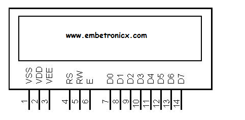
Pin Description
|
Pin No |
Function |
Name
|
||
|
1 |
Ground (0V) |
Ground |
||
|
2 |
Supply voltage; 5V (4.7V – 5.3V)
|
Vcc |
||
|
3 |
Contrast adjustment; through a variable resistor |
VEE |
||
|
4
|
Selects command register when low; and data register when high |
Register Select |
||
|
5 |
Low to write to the register; High to read from the register |
Read/write
|
||
|
6 |
Sends data to data pins when a high-to-low pulse is given |
Enable |
||
|
7 |
8-bit data pins
|
DB0 |
||
|
8 |
DB1 |
|||
|
9 |
DB2
|
|||
|
10 |
DB3 |
|||
|
11 |
DB4 |
|||
|
12
|
DB5 |
|||
|
13 |
DB6 |
|||
|
14 |
DB7
|
|||
|
15 |
Backlight VCC (5V) |
Led+ |
||
|
16 |
Backlight Ground (0V)
|
Led- |
The LCD module requires 3 control lines as well as either 4 or 8 I/O lines for the data bus. The user may select whether the LCD is to operate with a 4-bit data bus or an 8-bit data bus.
If a 4-bit data bus is used, the LCD will require a total of 7 data lines (3 control lines plus the 4 lines for the data bus). If an 8-bit data bus is used, the LCD will require a total of 11 data lines (3 control lines plus the 8 lines for the data bus).
The three control lines are referred to as EN, RS, and RW.
The EN line is called “Enable.” This control line is used to tell the LCD that you are sending it data. To send data to the LCD, your program should make sure this line is low (0) and then set the other two control lines and/or put data on the data bus.
|
|
|
When the other lines are completely ready, bring ENhigh (1) and wait for the minimum amount of time required by the LCD datasheet (this varies from LCD to LCD), and end by bringing it low (0) again.
The RS line is the “Register Select” line. When RS is low (0), the data is to be treated as a command or special instruction (such as a clear screen, position cursor, etc.).
When RS is high (1), the data being sent is text data which should be displayed on the screen. For example, to display the letter “T” on the screen, you would set RS high.
The RW line is the “Read/Write” control line. When RW is low (0), the information on the data bus is being written to the LCD. When RW is high (1), the program is effectively querying (or reading) the LCD. Only one instruction (“Get LCD status”) is a read command.
All others are write commands–so RW will almost always be low.
|
|
|
Finally, the data bus consists of 4 or 8 lines (depending on the mode of operation selected by the user). In the case of an 8-bit data bus, the lines are referred to as DB0, DB1, DB2, DB3, DB4, DB5, DB6, and DB7.
LCD COMMANDS
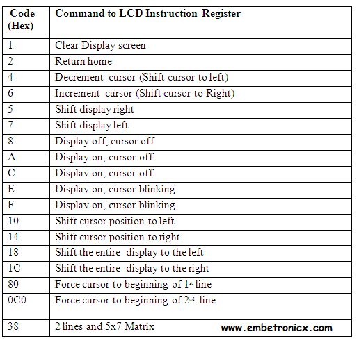 Now let’s move to programming.
LCD Interfacing with PIC16F877A – Circuit
- RS – Port C .0 (RC0)
- RW – Port C.1 (RC1)
- EN – Port C.2 (RC2)
- Data lines – Port B
Code
You can also download the whole project [Download Circuit and Code].
#include<pic.h>

#define rs RC0
#define rw RC1
#define en RC2
#define delay for(j=0;j<1000;j++)

int j;

void lcd_init();
void cmd(unsigned char a);
void dat(unsigned char b);
void show(unsigned char *s);


__CONFIG( FOSC_HS & WDTE_OFF & PWRTE_OFF & CP_OFF & BOREN_ON & LVP_OFF & CPD_OFF & WRT_OFF & DEBUG_OFF);

void main()
{
    unsigned int i;
    TRISB=TRISC0=TRISC1=TRISC2=0;
    lcd_init();
    cmd(0x8A); //forcing the cursor at 0x8A position
    show("WELCOME TO EmbeTronicX");
    while(1) {
        for(i=0;i<15000;i++);
        cmd(0x18);
        for(i=0;i<15000;i++);

    }
}

void lcd_init()
{
    cmd(0x38);
    cmd(0x0c);
    cmd(0x06);
    cmd(0x80);
}

void cmd(unsigned char a)
{
    PORTB=a;
    rs=0;
    rw=0;
    en=1;
    delay;
    en=0;
}

void dat(unsigned char b)
{
    PORTB=b;
    rs=1;
    rw=0;
    en=1;
    delay;
    en=0;
}

void show(unsigned char *s)
{
    while(*s) {
        dat(*s++);
    }
}
In our next tutorial, we will see how to use the LCD with 4 pins in PIC16F877A.
|
|
|
You can also read the below tutorials.
Embedded Software | Firmware | Linux Devic Deriver | RTOS
Hi, I am a tech blogger and an Embedded Engineer. I am always eager to learn and explore tech-related concepts. And also, I wanted to share my knowledge with everyone in a more straightforward way with easy practical examples. I strongly believe that learning by doing is more powerful than just learning by reading. I love to do experiments. If you want to help or support me on my journey, consider sharing my articles, or Buy me a Coffee! Thank you for reading my blog! Happy learning!
