
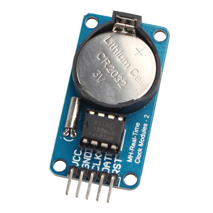
This article is a continuation of the series of tutorials on the PIC16F877A Microcontroller. The aim of this series is to provide easy and practical examples that anyone can understand. In the previous tutorial, we have interfaced RFID reader with PIC16F877A. In this tutorial, we are going to discuss RTC Interfacing with PIC16F877A. Before that, we should know about the RTC (DS1307) operations. Let’s start.
Table of Contents
Prerequisites
Components Required
RTC (DS1307)
Introduction
The DS1307 serial real-time clock (RTC) is a low-power, full binary-coded decimal (BCD) clock/calendar plus 56 bytes of NV SRAM. Address and data are transferred serially through an I²C, bidirectional bus. The clock/calendar provides seconds, minutes, hours, day, date, month, and year information. The end of the month date is automatically adjusted for months with fewer than 31 days, including corrections for leap year. The clock operates in either the 24-hour or 12-hour format with AM/PM indicator. The DS1307 has a built-in power sense circuit that detects power failures and automatically switches to the backup supply. Timekeeping operation continues while the part operates from the backup supply.
Features
- Completely Manages All Timekeeping Functions
- Real-Time Clock Counts Seconds, Minutes, Hours, Date of the Month, Month, Day of the Week, and Year with Leap-Year Compensation Valid Up to 2100
- 56-Byte, Battery-Backed, General-Purpose RAM with Unlimited Writes
- Programmable Square-Wave Output Signal
- Simple Serial Port Interfaces to Most Microcontrollers
- I2C Serial Interface
- Low Power Operation Extends Battery Backup Run Time
- Consumes Less than 500nA in Battery-Backup Mode with Oscillator Running
- Automatic Power-Fail Detect and Switch Circuitry
- 8-Pin DIP and 8-Pin SO Minimizes Required Space
- Optional Industrial Temperature Range: -40°C to +85°C Supports Operation in a Wide Range of Applications
- Underwriters Laboratories® (UL) Recognized

VCC, GND: These pins are used to provide power to the chip. When 5V is applied within normal limits, the device is fully accessible and data can be written and read. When a 3V battery is connected to the device and VCC is below 1.25 x VBAT, reads and writes are inhibited. However, the timekeeping function continues unaffected by the lower input voltage. As VCC falls below VBAT the RAM and timekeeper are switched over to the external power supply (nominal 3.0V DC) at VBAT.
X1-X2:Pins to connect the external 32.768kHz oscillator that provides the clock source to the chip.
Vbat: A 3.3v Lithium battery can be connected to this pin in order to provide the power source when the external supply voltage is not available. Battery voltage must be held between 2.0V and 3.5V for proper operation.
SCL: This pin must be connected to the SCL pin of the I2C Bus/Master.
SDA: This pin must be connected to the SDA pin of the I2C Bus/Master.
SQW/OUT: When enabled, the SQWE bit set to 1, the SQW/OUT pin outputs one of four square wave frequencies (1Hz, 4kHz, 8kHz, 32kHz).
- Note: The SCL, SDA, and SQW are open drain and must be pulled up with appropriate pull-up resistors
Connection circuit
DS1307 requires very few components to operate. One of the mandatory components is the crystal oscillator of 32.768kHz. The battery backup is optional as you can connect the power source to the Vbatt pin. But It is good to have the battery connected. When running on battery it only consumes 500 nA of current just for the operation of the clock and to maintain the content of NV RAM. You can use a coin cell-type battery as a backup source for DS1307.
The following image shows a typical connection diagram for DS1307 RTC.

DS1307 Memory
All the registers of DS1307 store value as BCD, i.e. if the clock is at 49 seconds then register 0x00 will show 0x49 as the binary coded decimal value of 49. This makes it easy for programmers to read and display numbers on LCD or serial terminals. So if you want to use register values of RTC then first convert the value from BCD to decimal and then use it.
The RTC keeps the date and time arranged in its memory as shown below:
 Register 0x07 is the control register for the square wave output pin. RS0 and RS1 bit select the output frequency as per the table below:

You can also use SQW/Out pin as a GPO pin when the SQW function of DS1307 is not used. Bit 7 controls the output level of the pin. If OUT bit is 1 then the OUT pin is high and when 0 OUT pin will be LOW.
RTC Interfacing with PIC16F877A
DS1307 uses I2C Protocol and acts as a slave device and I2C Master can read/write the register of RTC. To communicate with the slave device, the master needs the slave address of a device connected to the bus. DS1307 has a fixed slave address which makes it impossible to connect two RTC devices on the same bus, don’t worry occurrence of such a scenario is close to zero.
Slave address for I2C Write: 0b11010000 = 0xD0
Slave address for I2C Read: 0b11010001 = 0xD1
Circuit Diagram
LCD:
RS – RB0
RW – RB1
EN – RB2
Data Lines – Port D
EEPROM:
SDA – RC4
SCL – RC3

Programming
In this code, I’m printing the Time, Date, and day of the week. If you want to download the full project, please click here.
code.c
#include<pic.h>
#include"lcd.h"

__CONFIG( FOSC_HS & WDTE_OFF & PWRTE_OFF & CP_OFF & BOREN_ON & LVP_OFF & CPD_OFF & WRT_OFF & DEBUG_OFF);

unsigned char sec,min,hour,day,date,month,year;


void rtc_int();
void rtc_start();
void rtc_stop();
void rtc_ack();
void rtc_nak();
void rtc_res();
void rtc_send(unsigned char a);
void rtc_send_byte(unsigned char addr,unsigned char data);
unsigned char rtc_read();
unsigned char rtc_read_byte(unsigned char addr);
void waitmssp();
unsigned char convup(unsigned char bcd);
unsigned char convd(unsigned char bcd);


void main()
{
    lcd_init();

    show("Time:");
    cmd(0xc0);
    show("Date:");
    rtc_int();
    while(1) {
        sec  =rtc_read_byte(0x00);
        min  =rtc_read_byte(0x01);
        hour =rtc_read_byte(0x02);
        day  =rtc_read_byte(0x03);
        date =rtc_read_byte(0x04);
        month=rtc_read_byte(0x05);
        year =rtc_read_byte(0x06);

        cmd(0x85);
        dat(convup(hour));
        dat(convd(hour));
        dat(':');
        dat(convup(min));
        dat(convd(min));
        dat(':');
        dat(convup(sec));
        dat(convd(sec));

        cmd(0xc5);
        dat(convup(date));
        dat(convd(date));
        dat(':');
        dat(convup(month));
        dat(convd(month));
        dat(':');
        dat(convup(year));
        dat(convd(year));
        dat('/');
        dat(convup(day));
        dat(convd(day));

    }
}


void rtc_int()
{
    TRISC3=TRISC4=1;
    SSPCON=0x28;
    SSPADD= (((11059200/4)/100)-1);
}

void waitmssp()
{
    while(!SSPIF); // SSPIF is zero while TXion is progress
    SSPIF=0;
}

void rtc_send(unsigned char a)
{
    SSPBUF=a;
    waitmssp();
    while(ACKSTAT);
}

void rtc_send_byte(unsigned char addr,unsigned char data)
{
    rtc_start();
    rtc_send(0xD0);
    //rtc_send(addr>>8);
    rtc_send(addr);
    rtc_send(data);
    rtc_stop();
}

unsigned char rtc_read()
{
    RCEN=1;
    waitmssp();
    return SSPBUF;
}

unsigned char rtc_read_byte(unsigned char addr)
{
    unsigned char rec;
L:  rtc_res();
    SSPBUF=0xD0;
    waitmssp();
    while(ACKSTAT){goto L;}
    //rtc_send(addr>>8);
    rtc_send(addr);
    rtc_res();
    rtc_send(0xD1);
    rec=rtc_read();
    rtc_nak();
    rtc_stop();
    return rec;
}


void rtc_start()
{
    SEN=1;
    waitmssp();
}

void rtc_stop()
{
    PEN=1;
    waitmssp();
}

void rtc_res()
{
    RSEN=1;
    waitmssp();
}

void rtc_ack()
{
    ACKDT=0;
    ACKEN=1;
    waitmssp();
}

void rtc_nak()
{
    ACKDT=1;
    ACKEN=1;
    waitmssp();
}

unsigned char convup(unsigned char bcd)
{
    return ((bcd>>4)+48);
}

unsigned char convd(unsigned char bcd)
{
    return ((bcd&0x0F)+48);
}
LCD.H
#define rs RB0
#define rw RB1
#define en RB2
#define delay for(i=0;i<1000;i++)

int i;

void lcd_init();
void cmd(unsigned char a);
void dat(unsigned char b);
void show(unsigned char *s);

void lcd_init()
{
    TRISD=TRISB=0;
    cmd(0x38);
    cmd(0x0c);
    cmd(0x06);
    cmd(0x80);
}

void cmd(unsigned char a)
{
    PORTD=a;
    rs=0;
    rw=0;
    en=1;
    delay;
    en=0;
}

void dat(unsigned char b)
{
    PORTD=b;
    rs=1;
    rw=0;
    en=1;
    delay;
    en=0;
}

void show(unsigned char *s)
{
    while(*s) {
        dat(*s++);
    }
}
Output – RTC Interfacing with PIC16F877A
 [ Please find the output image Here ]
In our next tutorial, we will see how to interface the GPS module with PIC16F877A.
You can also read the below tutorials.

Embedded Software | Firmware | Linux Devic Driver | RTOS
Hi, I am a tech blogger and an Embedded Engineer. I am always eager to learn and explore tech-related concepts. And also, I wanted to share my knowledge with everyone in a more straightforward way with easy practical examples. I strongly believe that learning by doing is more powerful than just learning by reading. I love to do experiments. If you want to help or support me on my journey, consider sharing my articles, or Buy me a Coffee! Thank you for reading my blog! Happy learning!
Share this:

Discover more from EmbeTronicX
Subscribe to get the latest posts sent to your email.
This project working fine with proteus, but while doing with hardware it not showing present time, how I can work with hardware please help me
Hello Bharath,
It should work. Did you verified your hardware connections?
What if there is no ack from slave after address will the program stop executing further instructions if it so how can I overcome it
hi admin.. i have 1 doubt why do you use convup and convud functions i didnot clear.. if i try to set time using button when it reach 10 it print as 1; similarly 1: instead of 11 what is prblm https://uploads.disquscdn.com/images/836717ea80e6b3c7c970f38a4059820bc946cc8733a1934958a9f985e8c4d49d.png
Hi Ramesh,
Answer for Question 1:
All the registers of DS1307 stores value as BCD, i.e. if clock is at 49 seconds then register 0x00 which stores the seconds will show 0x49 as binary coded decimal. So If we want to print than we need to print 4 first and 9 second. How we can get the values? See below explanation.
Convup (convert the upper nibble of the byte to ASCII):
1. (0x49 >> 4) = 0x04 (We got value 4 using this step)
2. (0x04 + 48) = 52 (This is the value of 4 in ASCII. Now we can print this.)
Convd (convert the lower nibble of the byte to ASCII):
1. (0x49 & 0x0F) = 0x09 (We got value 9 using this step)
2. (0x09 + 48) = 57 (This is the value of 9 in ASCII. Now we can print this.)
Answer for question 2:
It should show properly for 10 and 11. Did you modified the source or your I2C working properly?
pls adjust my english because i no only little bit.
am not change anything in the source code i just added time set code with my knowledge and than my i2c is gud. below added my code for set the hour… if anything is worng pls teach me…thanks for your wonderful explanation..
if(set_button==0) // this s fr change the mode from time display to time edit.
{
cmd(0x01);
while(one==0) // its just for continuse loop and it will terminate end of the time set.
{
cmd(0x82);
show(“hrs”);
cmd(0x86);
show(“min”);
cmd(0x8a);
show(“sec”);
cmd(0xc2);
data(convup(hour)); // ur dat is modified as a data.
data(convd(hour));
cmd(0xc6);
data(convup(min));
data(convd(min));
cmd(0xca);
data(convup(sec));
data(convd(sec));
if(two==0) /*already i set two=0 in beginning of the time change so when set_button pressed automatically this statement execute but after the hr set operation it will not execute. because i will change the value of two. */
{
cmd(0xc9);
dat(‘ ‘);
cmd(0xc5);
dat(‘ ‘);
cmd(0xc1);
dat(‘>’);
if(down_button==0)
{
cmd(0xc2);
hour–; // i think here s the prblm.
}
else if(up_button==0)
{
cmd(0xc2);
hour++; //here also
}
if(set_button==0) //when we set the hour we should press the set_button so here hr set function will terminate.
{
two=1;
}
}
similarly min and sec operation……
}
}
Hi Ramesh,
Pls send your complete project code. Just compress and mail us to embetronicx@gmail.com. We will correct and send you. Because we need to test that first then only we can correct you.
Thank you.
would you please send me timer editing program using buttons and pic16f877a using pic
would you please send me…menu button programe for up button,down button,left button right button enter button in side timer edditing button and emergency button programe in pic16f877a
void rtc_send_byte(unsigned char addr,unsigned char data)
why use this function here..?
what is value of data..?
where u r call this function?
which compiler you are using?
MPLab