This article is a continuation of the series of tutorials on the PIC16F877A Microcontroller. The aim of this series is to provide easy and practical examples that anyone can understand. In the previous tutorial, we have interfaced the Bluetooth module with PIC16F877A. In this tutorial, we are going to see LDR Sensor Interfacing with PIC16F877A.
Table of Contents
Prerequisites
Before starting this tutorial we should know the below topics. If you know already, please go further.
Components Required
- PIC16F877A Development Board
- LDR Sensor
- LED
- LCD Module
Introduction
The dominance of street lights, outside lights, a number of indoor home appliances, and so on are typically operated and maintained manually on many occasions. This is not only risky, however additionally leads to wastage of power with the negligence of personnel or uncommon circumstances in controlling these electrical appliances ON and OFF. Hence, we can utilize the light sensor circuit for automatic switch OFF the loads based on daylight’s intensity by employing a light sensor. This article discusses in brief about what is a light-dependent resistor, how to interface with PIC16F877A.

What is a Light Dependent Resistor?
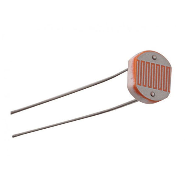
 An LDR or Light Dependent Resistor is also known as a photoresistor, photocell, photoconductor. It is one type of resistor whose resistance varies depending on the amount of light falling on its surface. When the light falls on the resistor, then the resistance changes. These resistors are often used in many circuits where it is required to sense the presence of light. Resistance will be decreased when the light increases. That means, In the daytime, the output resistance will be less compared to nighttime.
|
|
|
Working Principle of LDR
 This resistor works on the principle of photoconductivity. It is nothing but, when the light falls on its surface, then the material conductivity reduces, and also the electrons in the valence band of the device are excited to the conduction band. These photons in the incident light must have energy greater than the bandgap of the semiconductor material. This makes the electrons jump from the valence band to conduction.
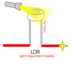
These devices depend on the light, when light falls on the LDR then the resistance decreases, and increases in the dark. When an LDR is kept in a dark place, its resistance is high and, when the LDR is kept in the light its resistance will decrease.
The figure below shows the curve between Resistance Vs Light Intensity curve for a particular light-dependent resistor.

Applications of LDR
Lighting switch
The most obvious application for an LDR is to automatically turn on a light at a certain light level. An example of this could be a street light or a garden light.
|
|
|
Camera shutter control
LDRs can be used to control the shutter speed on a camera. The LDR would be used to measure the light intensity which then adjusts the camera shutter speed to the appropriate level.
LDR Sensor Interfacing with PIC16F877A
LDR Sensor is an Analog Sensor. So we need to use ADC for interfacing. Please go through ADC tutorial.
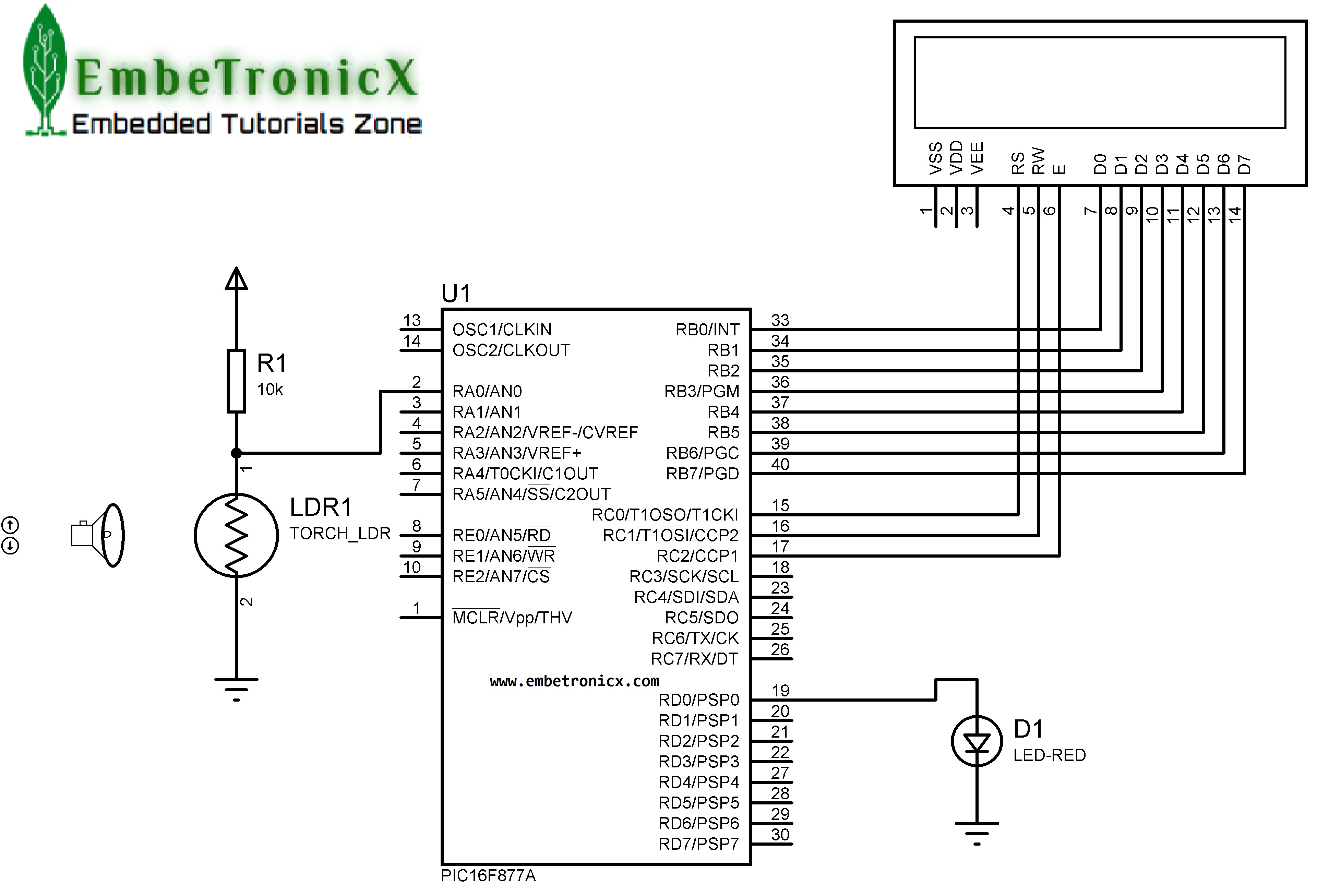
Circuit Diagram
LCD:
- RS: RC0
- RW: RC1
- EN: RC2
- Data Lines: RB0 – RB7
ADC:
- RA0 (AN0): LDR Sensor’s one end
LED:
|
|
|
- RD0 – LED
Source Code
This source code will control the LED-based on the Light Intensity. If Light Intensity is high, it turns OFF the LED and If Light Intensity is Low it turns ON the LED.
#include<pic.h>
#define delay for(i=0;i<=1000;i++)
#define rs RC0
#define rw RC1
#define e RC2
#define LED RD0

__CONFIG( FOSC_HS & WDTE_OFF & PWRTE_OFF & CP_OFF & BOREN_ON & LVP_OFF & CPD_OFF & WRT_OFF & DEBUG_OFF);

unsigned int adc();

void lcd_int();
void cmd(unsigned char a);
void dat(unsigned char b);
void show(unsigned char *s);

int i;

void main()
{
    unsigned int val;
    TRISB=TRISC=0;          //Port B and Port C is Output (LCD)
    TRISD = 0;              //Port D is output LED
    TRISA0=1;               //RA0 is input (ADC)
    lcd_int();
    while(1) {

        cmd(0x80);
        val = adc();
        show("LIGHT INT : ");
        if(val>150) {
            show("LOW ");
            LED = 1;
        } else {
            show("HIGH");
            LED = 0;
        }
    }
}

void lcd_int()
{
    cmd(0x38);
    cmd(0x0c);
    cmd(0x06);
    cmd(0x80);
}

void cmd(unsigned char a)
{
    PORTB=a;
    rs=0;
    rw=0;
    e=1;
    delay;
    e=0;
}

void dat(unsigned char b)
{
    PORTB=b;
    rs=1;
    rw=0;
    e=1;
    delay;
    e=0;
}

void show(unsigned char *s)
{
    while(*s) {
        dat(*s++);
    }
}

unsigned int adc()
{
    unsigned int adcval;

    ADCON1=0xc0;                    //right justified
    ADCON0=0x85;                    //adc on, fosc/64
    while(GO_nDONE);                //wait until conversion is finished
    adcval=((ADRESH<<8)|(ADRESL));    //store the result
    adcval=(adcval/3)-1;

    return adcval;
}
Output
In our next tutorial, we will see how to interface the Sound detecting sensor with PIC16F877A.
You can also read the below tutorials.
|
|
|
Embedded Software | Firmware | Linux Devic Deriver | RTOS
Hi, I am a tech blogger and an Embedded Engineer. I am always eager to learn and explore tech-related concepts. And also, I wanted to share my knowledge with everyone in a more straightforward way with easy practical examples. I strongly believe that learning by doing is more powerful than just learning by reading. I love to do experiments. If you want to help or support me on my journey, consider sharing my articles, or Buy me a Coffee! Thank you for reading my blog! Happy learning!
