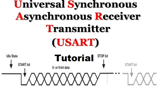
This article is a continuation of the series of tutorials on the PIC16F877A Microcontroller. The aim of this series is to provide easy and practical examples that anyone can understand. In our previous tutorial, we have seen PIC16F877A Timer Tutorial. In this tutorial, we are going to learn PIC16F877A Serial Communication (USART). USART (Universal Synchronous Asynchronous Receiver Transmitter) is one of the basic interfaces which provide a cost-effective simple and reliable communication between one controller to another controller or between a controller and PC.
Table of Contents
Prerequisites
If you are new to UART please go through our previous article about UART.
PIC16F877A Serial Communication Tutorial
PIC16F877A comes with inbuilt USART which can be used for Synchronous/Asynchronous communication. USART is a two-wire communication system in which the data flow serially. USART is also a full-duplex communication, which means you can send and receive data at the same time which can be used to communicate with peripheral devices, such as CRT terminals and personal computers.
The USART can be configured in the following modes:
- Asynchronous (full-duplex)
- Synchronous – Master (half-duplex)
- Synchronous – Slave (half-duplex)
But here We will be discussing only the UART (Asynchronous).
|
|
|
Registers used for Serial Communication
- TXSTA (Transmit Status And Control Register)
- RCSTA (Receive Status And Control Register)
- SPBRG (USART Baud Rate Generator)
- TXREG (USART Transmit Register)
- RCREG (USART Receiver Register)
TXSTA (Transmit Status And Control Register)
This register is used to configure the Serial communication for TX.
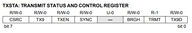
CSRC: Clock Source Select bit (Asynchronous mode: Don’t care).
TX9: 9-bit Transmit Enable bit
1 = Selects 9-bit transmission
0 = Selects 8-bit transmission
|
|
|
TXEN: Transmit Enable bit
1 = Transmit enabled
0 = Transmit disabled
SYNC: USART Mode Select bit
1 = Synchronous mode
0 = Asynchronous mode
BRGH: High Baud Rate Select bit
|
|
|
1 = High speed
0 = Low speed
TRMT: Transmit Shift Register Status bit
1 = TSR empty
0 = TSR full
TX9D: 9th bit of Transmit Data, can be a Parity bit
RCSTA (Receive Status And Control Register)
This register is used to configure the Serial communication for RX.
|
|
|
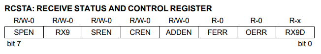
SPEN: Serial Port Enable bit
1 = Serial port enabled (configures RC7/RX/DT and RC6/TX/CK pins as serial port pins)
0 = Serial port disabled
RX9: 9-bit Receive Enable bit
1 = Selects 9-bit reception
0 = Selects 8-bit reception
|
|
|
SREN: Single Receive Enable bit (Asynchronous mode: Don’t care)
CREN: Continuous Receive Enable bit
Asynchronous mode:
1 = Enables continuous receive
0 = Disables continuous receive
ADDEN: Address Detect Enable bit
Asynchronous mode 9-bit (RX9 = 1):
1 = Enables address detection, enables interrupt and load of the receive buffer when RSR is set
0 = Disables address detection, all bytes are received and the ninth bit can be used as a parity bit
|
|
|
FERR: Framing Error bit
1 = Framing error (can be updated by reading RCREG register and receive next valid byte)
0 = No framing error
OERR: Overrun Error bit
1 = Overrun error (can be cleared by clearing bit CREN)
0 = No overrun error
RX9D: 9th bit of Received Data (can be parity bit but must be calculated by user firmware)
|
|
|
SPBRG (USART Baud Rate Generator)
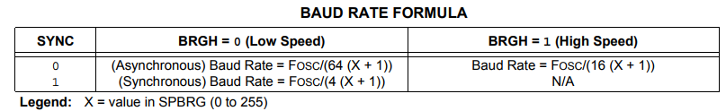
The main criteria for UART communication are its baud rate. Both the devices Rx/Tx should be set to the same baud rate for successful communication. This can be achieved by the SPBRG register. SPBRG is an 8-bit register that controls the baud rate generation. The SPBRG register controls the period of a free-running 8-bit timer. In Asynchronous mode, bit BRGH (TXSTA<2>) also controls the baud rate. In Synchronous mode, bit BRGH is ignored.
Given the desired baud rate and FOSC, the nearest integer value for the SPBRG register can be calculated using the below formula.
 Calculation:
My Fosc = 11.0592MHz (You can put your board Fosc)
Baud Rate = 9600
|
|
|
9600 = 11059200 / ( 64X + 64)
64X+64 = 1152
X = 17.
If we want to generate 9600 Baudrate (Fosc = 11.0592MHz) you have to set 17 to SPBRG Register.
TXREG (USART Transmit Register)
This is like a transmit buffer. But it is only an 8-bit register. So we have to place the character whatever we want to transmit via USART.
|
|
|
RCREG (USART Receiver Register)
This is like a receiver buffer. But it is only an 8-bit register. So we can take the character whatever we microcontroller received via USART.
Programming
Initializing USART
- Configure the TXSTA Register for Transmit
- Configure the RCSTA Register for Receiver
- Feed the value for baud rate that you have calculated using the above formula to SPBRG Register
void ser_int()
{
    TXSTA=0x20; //BRGH=0, TXEN = 1, Asynchronous Mode, 8-bit mode
    RCSTA=0b10010000; //Serial Port enabled,8-bit reception
    SPBRG=17;           //9600 baudrate for 11.0592Mhz
    TXIF=RCIF=0;
}
Transmit
- Load the new char to be transmitted into THR.
- Wait till the char is transmitted. TXIF will be set when the TXREG is empty.
- Clear the TXIF for the next cycle.
void tx(unsigned char a)
{
    TXREG=a;
    while(!TXIF);
    TXIF = 0;
}
Receive
- Wait till the Data is received. RCIF will be set once the data is received in the RCREG register.
- Clear the receiver flag(RCIF) for the next cycle.
- Copy/Read the received data from the RCREG register.
unsigned char rx()
{
    while(!RCIF);
    RCIF=0;
    return RCREG;
}
Full code
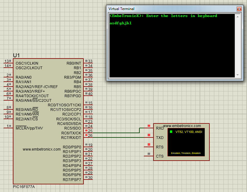
This program first transmits some strings (EmbeTronicX: Enter the letters on the keyboard). Then it will act as an echo. Whatever we pressed on the keyboard, it will print that in the serial terminal.
#include<htc.h>


__CONFIG( FOSC_HS & WDTE_OFF & PWRTE_OFF & CP_OFF & BOREN_ON & LVP_OFF & CPD_OFF & WRT_OFF & DEBUG_OFF);


void ser_int();
void tx(unsigned char);
unsigned char rx();
void txstr(unsigned char *);

void main()
{
    TRISC6=0;   //Output (TX)
        TRISC7=1;   //Input (RX)
    ser_int();
    txstr("(EmbeTronicX): Enter the letters in keyboard\n\r\r");
    while(1) {
        tx(rx());
    }
}

void ser_int()
{
    TXSTA=0x20; //BRGH=0, TXEN = 1, Asynchronous Mode, 8-bit mode
    RCSTA=0b10010000; //Serial Port enabled,8-bit reception
    SPBRG=17;           //9600 baudrate for 11.0592Mhz
    TXIF=RCIF=0;
}

void tx(unsigned char a)
{
    TXREG=a;
    while(!TXIF);
    TXIF = 0;
}

unsigned char rx()
{
    while(!RCIF);
    RCIF=0;
    return RCREG;
}

void txstr(unsigned char *s)
{
    while(*s) {
        tx(*s++);
    }
}
Output
In our next tutorial, we will see how to use the ADC in PIC16F877A.
You can also read the below tutorials.
|
|
|
Embedded Software | Firmware | Linux Devic Deriver | RTOS
Hi, I am a tech blogger and an Embedded Engineer. I am always eager to learn and explore tech-related concepts. And also, I wanted to share my knowledge with everyone in a more straightforward way with easy practical examples. I strongly believe that learning by doing is more powerful than just learning by reading. I love to do experiments. If you want to help or support me on my journey, consider sharing my articles, or Buy me a Coffee! Thank you for reading my blog! Happy learning!
