
Table of Contents
Introduction
Ethernet was created in 1973 by Robert Metcalfe and became a global standard in 1983, known as IEEE 802.3. Ethernet protocol is a system that allows computers and devices to communicate with each other over a wired network. It is like a set of rules that organize how data is sent and received.
Ethernet divides data into small packets called frames, which contain information about where the data is coming from and where it needs to go. It uses cables to connect devices and is known for being fast, reliable, and cost-effective. It works in homes, offices, and even big data centers.
Modern Ethernet networks can transfer data at speeds ranging from 10 Mbps to 100 Gbps or more, making it one of the most widely used communication technologies today.
Understanding Ethernet Protocol in the OSI Model
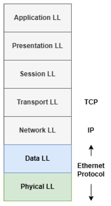
Ethernet protocol operates at two key layers of the OSI model:
- Data Link Layer (Layer 2)
- Physical Layer (Layer 1).
These layers work together to ensure data is sent and received efficiently over a wired network. Additionally, higher-level protocols like TCP/IP rely on Ethernet to function as the foundation of modern communication.
Data Link Layer (Layer 2)
At the Data Link Layer, Ethernet is responsible for framing, addressing, and controlling access to the network. It ensures that data is properly formatted and delivered to the correct device.
This layer has two sublayers: Media Access Control (MAC) and Logical Link Control (LLC).
Media Access Control (MAC) Sublayer
The MAC sublayer controls how devices share access to the network and uses unique MAC addresses to identify devices. When a computer wants to send data to another, it includes the receiver’s MAC address to ensure the data reaches the correct destination. It also adds a Frame Check Sequence (FCS) to detect any errors in the data during transmission.
E.g. If Computer A wants to send data to Computer B, it uses the MAC address of Computer B to deliver the data.
Logical Link Control (LLC) Sublayer
The LLC sublayer provides flow control and error checking, allowing higher-layer protocols like IP to work seamlessly regardless of the hardware being used.
Physical Layer (Layer 1)
The Physical Layer is where data is physically transmitted as raw bits (1s and 0s) over a network medium, such as copper cables or fiber optics. This layer defines the types of cables, connectors, and signaling methods used in Ethernet communication. For example, when a computer sends data, the Physical Layer converts it into electrical pulses (for copper cables) or light signals (for fiber optics) and transmits it to the connected device. Standards like Cat5e and Cat6 cables determine how fast and efficiently data can travel.
Ethernet Frame Format
Ethernet frames are like the envelopes used to send letters over a network. Each part of the frame has a specific purpose to ensure the data (or message) gets delivered correctly. Imagine you’re sending a letter to a friend, Bob. To make sure the letter reaches Bob and he understands it, you need to include specific details, such as Bob’s address, your address, and a clear message.
Ethernet transmits data as a series of electrical voltage signals (for copper cables) or light signals (for fiber optics). Each part of the Ethernet frame format corresponds to specific voltage patterns that encode the data, allowing devices to interpret the information accurately
Ethernet uses a technique called line encoding to convert binary data (0s and 1s) into voltage levels for transmission. For copper cables:
- A 1 might be represented by a positive voltage (e.g., +2.5V).
- A 0 might be represented by a negative voltage (e.g., -2.5V).

The Preamble: (Setting the Stage)
Before sending any actual data, the sender needs to prepare the receiver. This is where the preamble comes in.
- The preamble is a series of alternating 1s and 0s (101010…) for 7 bytes that acts like a warm-up signal, helping the receiver synchronize its internal clock with the sender’s clock.
Imagine tuning your car radio to catch a song. If the signal isn’t clear, the music will sound distorted. The preamble is like the radio adjusting itself to ensure the song plays smoothly.
Start Frame Delimiter (SFD): (The Green Light)
After the preamble, we have the Start Frame Delimiter (SFD), which is a special code marking the beginning of the actual data. The SFD is a special byte (10101011) that signals the end of the preamble and the start of the actual data. The final two bits (11) indicate a deviation from the alternating pattern, signaling the start of the frame.
Destination Address: (Who Is the Message For?)
Every Ethernet frame needs a destination, just like every letter needs an address.
- The destination address specifies the unique MAC address (6 bytes) of the device that should receive the frame.
- For instance, if you’re sending a file to Bob’s computer, the frame includes Bob’s MAC address to ensure the message gets delivered to him.
Source Address: (Where Is the Message From?)
The source address is like your return address on a letter. This is also the MAC address (6 bytes) of the device.
- It tells the receiver (e.g., Bob) who sent the data.
- This way, Bob knows where to send a response if needed.
Type/Length: What’s Inside the Envelope?
This 2 byte of field indicates either the type of data being sent or the length of the data field.
- For example, it might specify that the data is an IP packet or an ARP request.
- Think of it as writing “This is a birthday card” on the outside of an envelope to give the recipient an idea of what’s inside. 4
Data: (The Actual Message)
The data field is where the real message resides. It can contain anything, like a simple text, an image, or even a video file. The size of data can vary from 46 bytes to 1500 bytes.
Frame Check Sequence (FCS): (Is Everything Okay?)
At the end of the frame, there’s the Frame Check Sequence (FCS) (4 bytes), which is used to detect errors in the transmitted data. If the receiver detects an error, it might discard the frame and rely on higher-layer protocols to request a retransmission.
Minimum and Maximum Ethernet Frame Sizes
The size of an Ethernet frame is defined by the IEEE 802.3 standard. The minimum size ensures compatibility and proper collision detection in the network, while the maximum size is designed to balance performance and efficiency.
- Minimum Ethernet Frame Size:
○ 64 bytes (512 bits), including all fields.
○ If the data is smaller than 46 bytes, padding is added to meet the minimum size requirement. - Maximum Ethernet Frame Size:
○ 1518 bytes (12,144 bits), including all fields.
○ For standard Ethernet, the maximum data field (payload) is 1500 bytes.
○ Jumbo Frames (used in some modern networks) can extend this limit, supporting payloads up to 9000 bytes or more.
How the Preamble Helps with Clock Synchronization
In Ethernet communication, the preamble helps the receiver synchronize its internal clock with the sender’s clock, ensuring accurate interpretation of the transmitted data.
Why Synchronization Matters
Without clock synchronization, the receiver might misinterpret the incoming signal. For instance:
- A 1 might be read as a 0, or vice versa, due to timing discrepancies.
- This could lead to corrupted data or communication failures.
The Role of the Preamble
The preamble is a sequence of 7 bytes (56 bits), made up of alternating 1s and 0s (e.g., 101010…). It is followed by a Start Frame Delimiter (SFD), a special 1-byte pattern (10101011), which signals the beginning of the actual frame. Here’s how this works:
- Regular Pattern for Detection:
○ The predictable pattern of alternating 1s and 0s provides a clear signal to the receiver that a frame is about to arrive.
○ This pattern acts like a “wake-up call” to the receiver, saying, “Get ready, data is coming!” - Clock Recovery:
○ Ethernet communication relies on both the sender and receiver having synchronized clocks.
○ The receiver uses the preamble to align its internal clock’s frequency and phase with the sender’s clock.
○ This ensures that the receiver interprets the binary data (1s and 0s) correctly and doesn’t misread it due to timing mismatches.
CSMA/CD (Carrier Sense Multiple Access with Collision Detection)
How Collision Detection Works in CSMA/CD
In an Ethernet network that uses CSMA/CD, the process of detecting and handling collisions plays a crucial role in ensuring that data transmission is efficient. This protocol is designed for situations where multiple devices share the same transmission medium (like older Ethernet networks using hubs).
Carrier Sense: (Listening for Traffic)
Before a device sends data, it first checks the network to see if any other device is currently transmitting. It “listens” (uses a network interface card (NIC) to sense voltage or light pulses) to the network channel. If it detects that the channel is busy (another device is transmitting), it waits for the channel to be clear.
Multiple Access: (Starting to Transmit)
Once the device detects that the channel is clear (no one else is transmitting), it begins transmitting its data. However, other devices on the network can also “hear” the transmission end and might decide to transmit their own data at the same time.
It’s like several people in the room thinking the others are waiting and all deciding to speak simultaneously. This is where potential collisions arise.
Collision Detection: (Spotting the Overlap)
As the device sends its data, it constantly monitors the network to detect if a collision has occurred. A collision happens when two devices transmit data at the same time, causing their signals to interfere with each other. This results in corrupted data that cannot be interpreted correctly.
For example, if two people in the room start talking at the same time, their words overlap and become jumbled. Similarly, when the device detects a collision, it notices unusual patterns or “spikes” in the voltage on the network, indicating interference.
Voltage Pattern during Collision
When two signals collide, the voltage pattern on the network becomes irregular. Below is a simplified view of what the voltage might look like during and after a collision:
- Before Collision: The signal would be a smooth, periodic voltage wave, representing a single data stream.
- During Collision: Both devices transmitting at once results in a complex waveform with irregular peaks and troughs, causing data corruption.
- After Collision: The voltage spikes and fl uctuations would be detected by the device, which then knows to stop transmitting.
The key point here is that voltage spikes caused by the collision are the indicator that something went wrong, and the devices must take action.
Backoff and Retry: (Reattempting the Transmission)
When a collision is detected, the device immediately stops its transmission. But it doesn’t just retry right away. Instead, it waits for a random period before trying to send the data again. This period is known as backoff. By waiting for a random time, it reduces the chance that two devices will try to send data at the exact same time again.
This is similar to the people in the room who, after realizing they spoke at once, take a moment to calm down before trying to speak again, but this time, they wait a little randomly to avoid speaking at the same time.
When Is Collision Detection Used?
- Half-Duplex Ethernet: CSMA/CD is primarily used in half-duplex systems, where the network can only transmit in one direction at a time. For example, when multiple devices share the same Ethernet cable or hub, a collision might happen if two devices try to send data simultaneously.
- Full-Duplex Ethernet: In full-duplex systems, the devices can send and receive data at the same time, effectively eliminating collisions. In these modern Ethernet systems (like those using switches), each device has a dedicated communication channel, and CSMA/CD is not needed.
Ethernet Standards
Over time, various Ethernet standards have been developed to support different speeds and technologies. The most common standards are:
- 10BASE-T: 10 Mbps
- 100BASE-T: 100 Mbps
- 1000BASE-T: 1 Gbps
- 10GBASE-T: 10 Gbps 8
Application of Ethernet Protocol
- Industrial Automation
An assembly line where multiple robots and machines need to communicate with each other and with central monitoring systems to track production progress, perform quality checks, and detect any issues instantly. - IoT
Smart home devices such as thermostats, lights, and security cameras that use Ethernet for high-speed and reliable data transmission. These devices can be monitored and controlled remotely via the internet. - Automotive
Modern vehicles are equipped with Ethernet-based systems for faster communication between sensors (like cameras, radar, and lidar) that support autonomous driving or driver-assist technologies. - Data Centers
Cloud service providers (such as AWS, and Google Cloud) use Ethernet to connect thousands of servers and devices in their data centers, ensuring reliable and high-speed data transfer for hosting websites, and applications, and storing user data. - Security System
A city-wide security system with multiple surveillance cameras placed in different locations. These cameras send live video feeds via Ethernet to a central control room for monitoring and threat detection.
Summary
Ethernet has long been the backbone of networking technologies, and its role extends into embedded systems, where it is often used for communication between embedded devices, IoT networks, and other digital systems.
Author: Raghav Jha
Linkedin: https://www.linkedin.com/in/raghav-jha-599552188/
About me: I’m Raghav Jha, a Senior Embedded Software Engineer with approx 5 years of experience in embedded systems. Skilled in C, Embedded C, C++, FreeRTOS, BSP development, and cybersecurity.
You can also read the below tutorials.
Embedded Software | Firmware | Linux Devic Driver | RTOS
Hi, I am a tech blogger and an Embedded Engineer. I am always eager to learn and explore tech-related concepts. And also, I wanted to share my knowledge with everyone in a more straightforward way with easy practical examples. I strongly believe that learning by doing is more powerful than just learning by reading. I love to do experiments. If you want to help or support me on my journey, consider sharing my articles, or Buy me a Coffee! Thank you for reading my blog! Happy learning!
Share this:

Discover more from EmbeTronicX
Subscribe to get the latest posts sent to your email.