This article is a continuation of the Series on STM32 Bootloader and carries the discussion on Bootloader design and implementation. The aim of this series is to provide easy and practical examples that anyone can understand. This post is STM32 Firmware Update Over the Air (FOTA) – Bootloader Tutorial Part 6 where we will do STM32 Wireless Firmware Update.
We have attached the video explanation at the bottom of this post. We have posted another variant of the Bootloader development using the STM32F103. Please check that and learn that too.
Table of Contents
Wireless STM32 Firmware Update
In this STM32 Wireless Firmware Update example, we will be using the concepts that have been explained already in the tutorials below. So I would request you to go through those tutorials first if you are not familiar with those topics.
- Bootloader Basics
- Bootloader and Application Design
- Simple Bootloader Implementation
- Updating the application using the bootloader
- Add Slot 0 and Slot 1 to the bootloader
We are providing the video format of this Bootloader series. Please check out the video playlist. You can also get the source code of this tutorial from GitHub.
Hardware Required
We have our own EmbeTronicX Store called ChipTronicX. You can purchase the hardware from ChipTronicX.
|
|
|
- STM32F767Zi Nucleo (You can use any STM32 boards. But use the addresses and flash size based on your controller).
- LED (If you don’t have onboard LED)
- BT-05 or HM-10 Bluetooth Module
STM32 Firmware Update Over the Air
What did we do in our previous tutorial?
Previously, the STM32 Nucleo board was connected to the desktop or laptop using the USB to serial converter. So, both are communicating through the cable. The firmware or application was sitting on the computer.
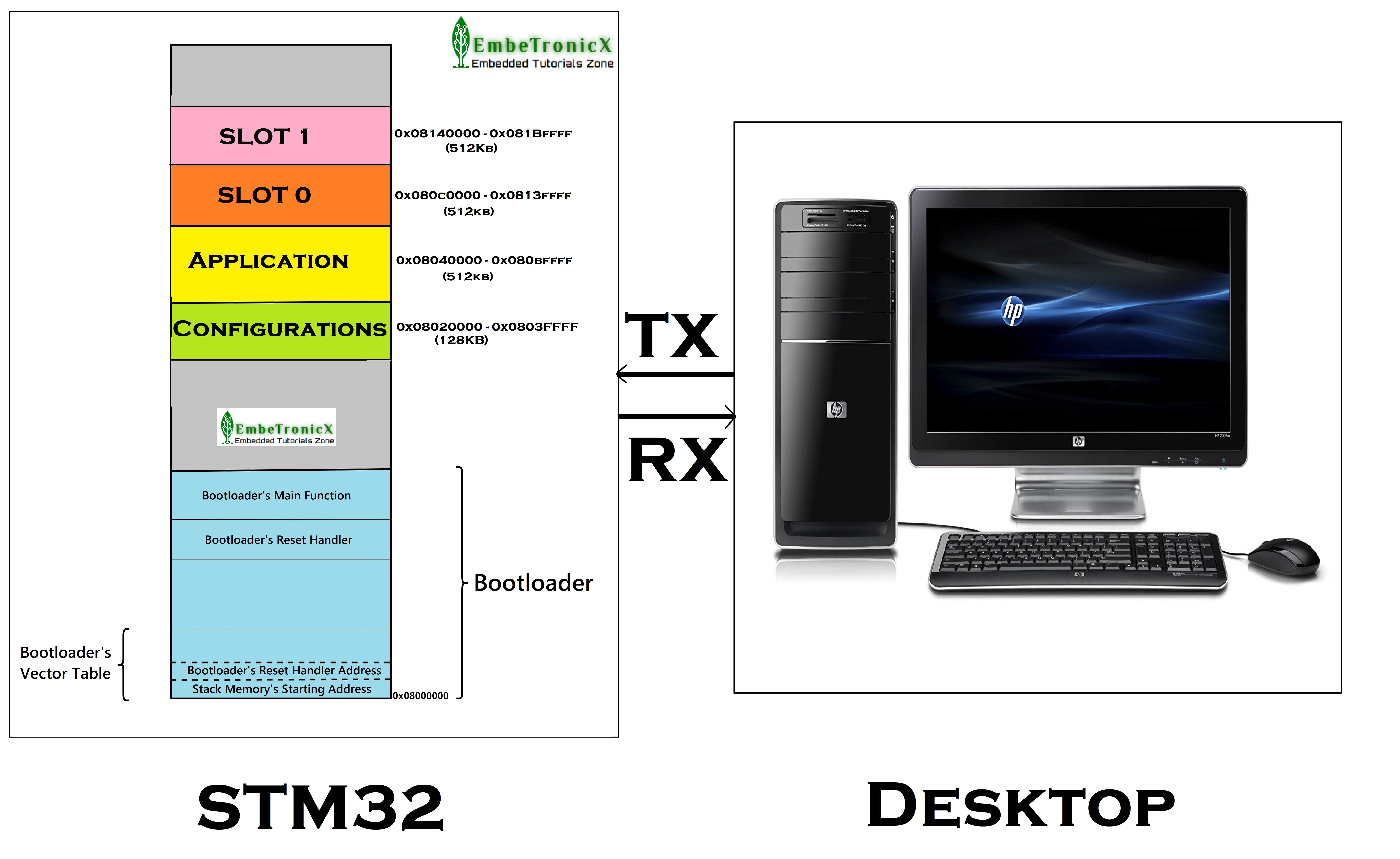
The firmware or application is parsed using the PC application which has been developed previously. If we want to update the firmware, then we will press the user boot button when the bootloader starts. Now the bootloader will be waiting for the data over the UART.
The PC application sends the data to the STM32 by following our protocol. The bootloader writes the received data to either slot 0 or slot 1. After that, the bootloader copies the data from the slot to the application area and boots it. This is how we are updating our firmware or application with wire.
Let’s consider this scenario. When you deploy your product into the field, do you like to connect the computer and STM32 board and then flash the firmware every time?
|
|
|
No, right. You may like it, but I never like this process. Because I don’t want to touch the hardware every time. To avoid that, can we update the firmware without wire? Yes. We will see how to do that in this tutorial.
Concept of this tutorial
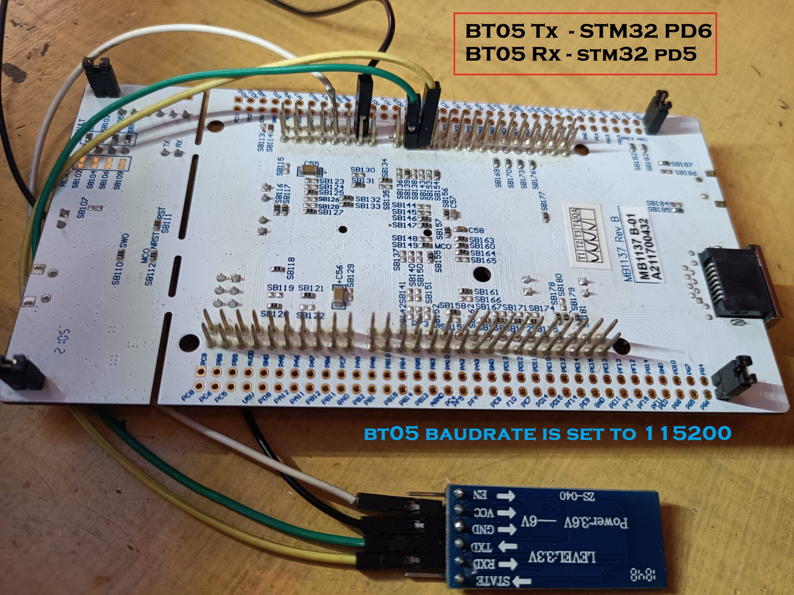
In this tutorial, I have connected the STM32 board and BT-05 Bluetooth board. You can use any Bluetooth chip like ESP32, HM10 Module, etc. which supports BLE. These BT-05 pins are connected to STM32’s USART 2 pins. The BT-05 gives you the received Bluetooth data via UART to the STM32.
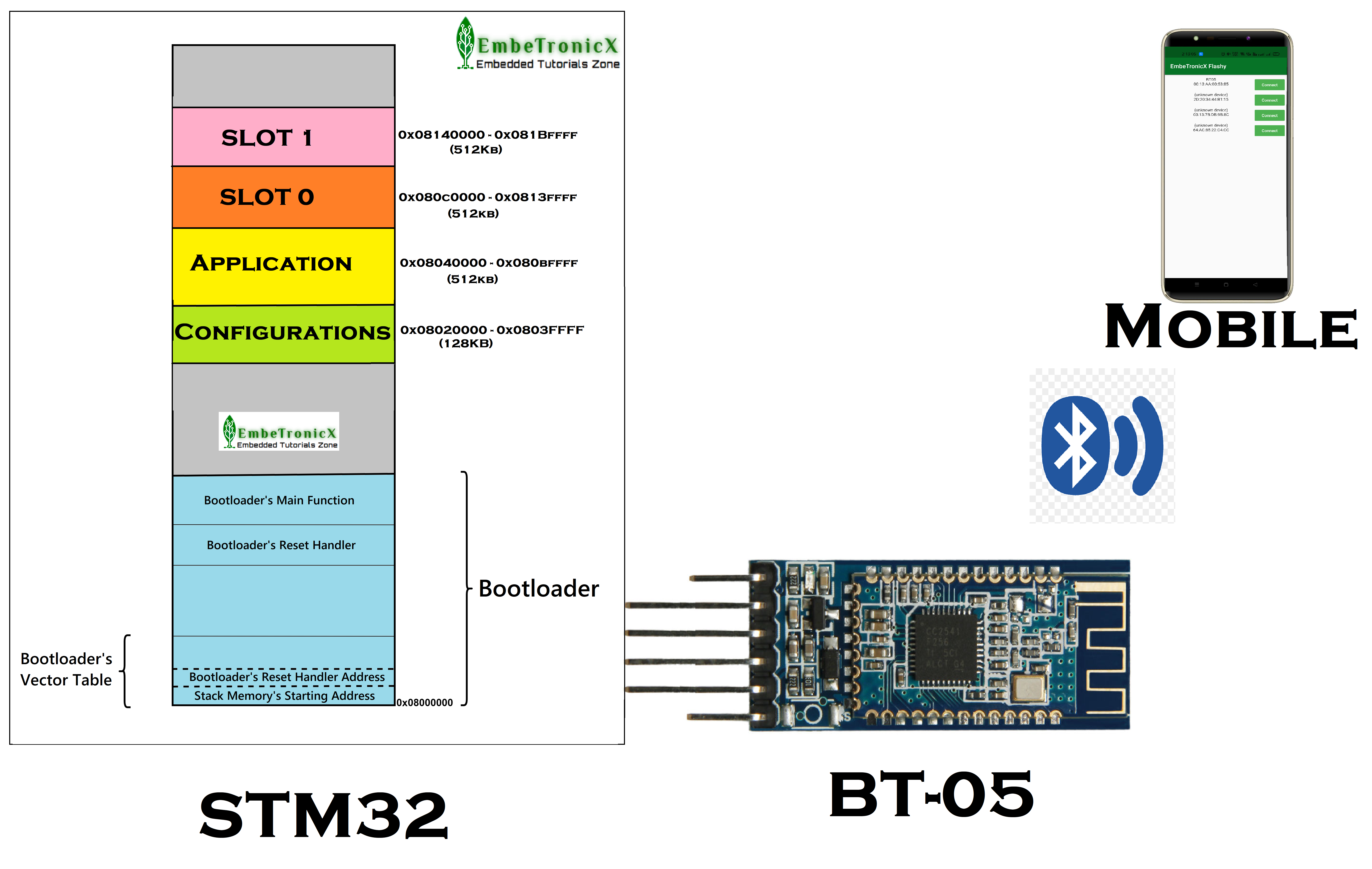
The mobile application is connected to the BT-05 via Bluetooth. When the chip powers up, the bootloader gives controls to the application that blinks the LED. When the OTA is available, We don’t have to press the reset button and user boot button.
The mobile app will inform the BT-05 via BLE. We have developed the Android application for this purpose. Then the Bluetooth module sends that data to the STM32 via USART 2. Then the application gives the control to the Bootloader. So, that the bootloader can start the OTA process.
|
|
|
Then the mobile application sends the firmware package data to the STM32 Bootloader via Bluetooth. And it writes data to slot 0 or slot 1. Then it copies the data to the application area and runs the new application.
In this tutorial, I won’t touch the Bootloader. So, it will remain the same as our previous tutorial (0.3 version).
Add the OTA feature to the Application
Now we will add the OTA feature to the Application so that, it will give control to the Bootloader when Firmware OTA is available. I am enabling the USART 2. So, make the PD6 as RX and PD5 as TX in the Blinky.ioc file. Please refer to this video for a better understanding.
Code:
#include "etx_ota_update.h"

#define MAJOR 0   //APP Major version Number
#define MINOR 4   //APP Minor version Number

void HAL_UART_RxCpltCallback(UART_HandleTypeDef *huart)
{
  if (huart->Instance == USART2)
  {
    if( !strncmp("ota", (char*)rx_buf, 3) )
    {
      printf("Received OTA Request from Mobile Application\r\n");

      /* Update the reboot reason as OTA request */

      /* Read the configuration */
      ETX_GNRL_CFG_ cfg;
      memcpy( &cfg, (ETX_GNRL_CFG_*) (ETX_CONFIG_FLASH_ADDR), sizeof(ETX_GNRL_CFG_) );

      //update the reboot reason
      cfg.reboot_cause = ETX_OTA_REQUEST;

      /* write back the updated config */
      write_cfg_to_flash( &cfg );

      // Reset the controller
      HAL_NVIC_SystemReset();
    }
    else
    {
      HAL_UART_Receive_IT(&huart2, rx_buf, 3);
    }
    memset(rx_buf, 0, sizeof(rx_buf));
  }
}

int main(void)
{
  .....
  HAL_UART_Receive_IT(&huart2, rx_buf, 3);
  .....
}
I have added (modified) the above code to the application which has been created with the help of the previous tutorial – STM32 Bootloader Source Code
Code Explanation:
We will have to receive the UART data asynchronously. So, I am using the interrupt method instead of polling. I have added the HAL_UART_Receive_IT() function which tells you to receive the 3 bytes of data from the USART2.
|
|
|
Whenever we receive the 3 bytes, this HAL_UART_RxCpltCallback() function will be called. There we will have to check that we received data from USART2. If so, check that we have received the string “ota“. The Android app will send the string “ota” to STM32’s application to start the OTA process.
Then the application changes the reboot cause as OTA Request and writes it to the flash.
After that, it resets the controller. Now the bootloader will take care of the OTA process. If we didn’t receive the string “ota“, then we again scheduled the Rx.
Now, when the bootloader starts, it will read the reboot cause as an OTA Request. So, it will wait for the OTA data.
Build the Application and Flash it to the STM32 using our previous tutorial’s steps.
|
|
|
After the flashing, See, the 0.4 application is running.
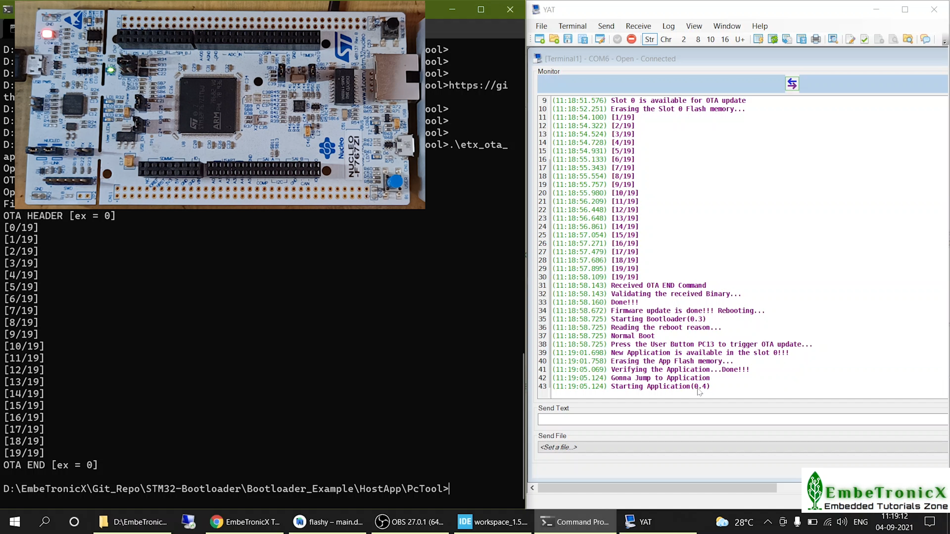
Now, this app supports OTA. Let’s verify this OTA update.
STM32 OTA Example
Connection Diagram
I have connected the BT-05 to STM32’s USART 2. Please check the connection using the below image.
|
|
|
I have changed the baud rate of the BT-05 to 115200 bits using the AT command “baud 8“. The default baud rate is 9600.
Let’s create a new application to verify the OTA process.
Create new application
I have added a new Red LED blinking feature to the application. Please check this video to see how I have added the Red LED.
Build the new application and copy it to the Mobile Phone.
Android Application
We have developed a simple Android application using Flutter to demonstrate this OTA update. You can get the Android application source code from GitHub.
|
|
|
I have just simply learned the flutter in a few days and wrote this app. So, this Android app is a very basic app and it may have many bugs.
Even if you click the cancel button during the transmission, it won’t react. Because I am running a for loop which makes the UI hang. I don’t know the proper way to handle this.
If you are able to fix this problem, please give us the solution. Also, we are not taking care of the response that STM32 sends for each chunk. You can add that too if you are able to fix that.
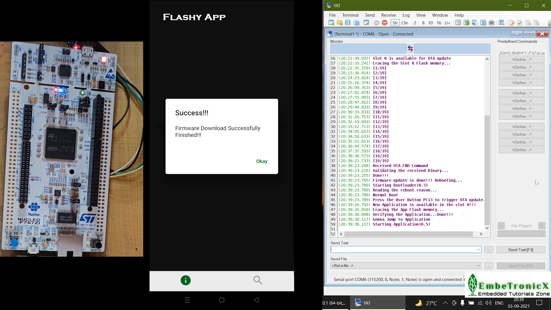
STM32 Firmware Update Over the Air (FOTA) – Demo
Open the Flashy App. Connect to BT05. There are many characteristics available. I am going to use the last custom characteristic for our communication. Select write. Then select the binary file that we want to flash. Then start the OTA process. Please check the video for reference.
This OTA process took almost 18 minutes. Yes, I agree. For just a 20Kb file, it is taking that much time. It is huge. We can optimize it. I am leaving this optimization to you.
|
|
|
See, the new application has been flashed successfully. The new app 0.5 is running now. And see the LEDs. Both Blue and Red LEDs are blinking.
That’s it. We have flashed the new application over the air (STM32 Firmware Update Over the Air). Let’s celebrate it.
You can get the all source code from GitHub.
Video Explanation
Please check our video explanation below.
|
|
|
In our next tutorial, we will see how to update the firmware using the SD card with SPI communication.
We have posted another variant of the Bootloader development using the STM32F103. Please check that and learn that too.
You can also read the below tutorials.
|
|
|
Embedded Software | Firmware | Linux Devic Deriver | RTOS
Hi, I am a tech blogger and an Embedded Engineer. I am always eager to learn and explore tech-related concepts. And also, I wanted to share my knowledge with everyone in a more straightforward way with easy practical examples. I strongly believe that learning by doing is more powerful than just learning by reading. I love to do experiments. If you want to help or support me on my journey, consider sharing my articles, or Buy me a Coffee! Thank you for reading my blog! Happy learning!
