This article is a continuation of the series of tutorials on the PIC16F877A Microcontroller. The aim of this series is to provide easy and practical examples that anyone can understand. In the previous tutorial, we have interfaced the Fire detecting sensor with PIC16F877A. In this tutorial, we are going to see Rain Sensor Interfacing with PIC16F877A.
Table of Contents
Prerequisites
Before starting this tutorial we should know the below topics. If you know already, please go further.
Components Required
- PIC16F877A Development Board
- Rain Drop Sensor
- LCD Module (To print the Sensor output)
Introduction
Water is a basic need in everyone’s life. Saving water and proper usage of water is very important. Here is an easy project which will display the rain status, so that we can make some actions for rainwater harvesting or take out our clothes from outside, before its getting wet due to rain. You can also add the alarm circuit to this project.
Rainwater detector will detect the rain and make an alert; rain water detector is used in the irrigation field, home automation, communication, automobiles, etc. It may, however, be tinkered for a number of other applications.
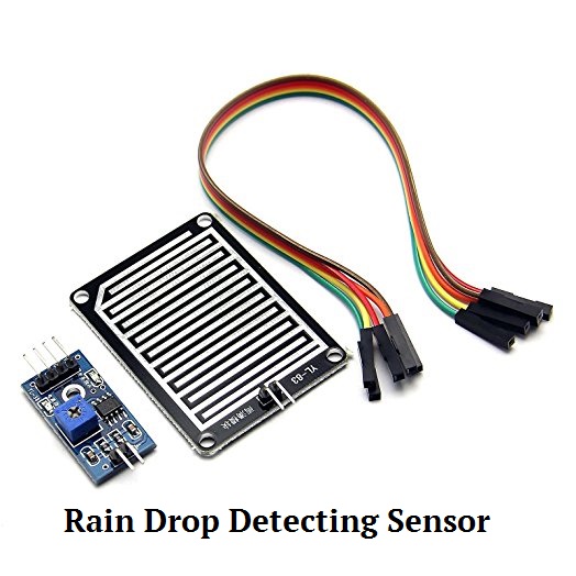
Rain Drop Sensor
A raindrop sensor is basically a board on which nickel is coated in the form of lines. It works on the principle of resistance.
|
|
|

Rain Sensor module allows to measure moisture via analog output pins and it provides a digital output when a threshold of moisture exceeds. The module is based on the LM393 op-amp.
Specifications
- Adopts high quality of RF-04 double-sided material.
- Area: 5cm x 4cm nickel plate on side,
- Anti-oxidation, anti-conductivity, with long use time;
- Comparator output signal clean waveform is good, driving ability, over 15mA;
- The PCB of this electronic circuit has a potentiometer. The Sensitivity of the Digital pin can be varied using the potentiometer
- Working voltage 5V;
- Output format: Digital switching output (0 and 1) and analog voltage output AO;
- With bolt holes for easy installation;
- Small board PCB size: 3.2cm x 1.4cm;
- Uses a wide voltage LM393 comparator
Working Principle of Rain Drop Sensor
The rain sensor used is composed of two parts. The first one is the effective sensor, which is a plaque that is exposed to the rain. This plaque has two strips of conductive material, very close to each other, but without touching.
So, if we apply a voltage between the two strips, it will be an open circuit. Nevertheless, when we expose this surface to the rain, the water that falls closes the circuit between the strips and a different voltage can be measured.
Keep in mind that when the raindrops the two strips will not be short-circuited because water is not a perfect conductor. So, this sensor will act as a variable resistor, which will be lower when more waterfalls on the surface, connecting the stripes in more points. I’ve tested the resistance of the sensor with a multimeter after applying some water drops and it was about 65 kΩ.
|
|
|
The second part is the electronic circuit board responsible to process the signal from the plaque and expose it as two signals, one digital and another analog.
So, we have a digital output pin, which operates as active-low, indicating that rain is being detected or not. Since this pin is active-low, it will have a value of GND when rain is detected, and VCC when rain is not detected.
Since, as stated, the rain sensor will act as a variable resistor, its output will be an analog voltage that needs to be converted to this digital one. So, the electronic circuit uses an LM393 comparator to compare this analog voltage to a certain threshold and output GND or VCC accordingly.
The PCB of this electronic circuit has a potentiometer that we can change to adjust this threshold, making the sensor more or less sensible to the raindrops.
Additionally, the sensor has an analog output with a variable voltage that depends on the resistance of the sensor and thus, on the amount of water on it.
|
|
|
This module can work with voltage supplies of both 3.3 V and 5 V. Just keep in mind that there can be different versions from different manufacturers.
Rain Sensor Interfacing with PIC16F877A
Connection
Rain Sensor
- Vcc – 5v
- GND – Ground
- DO – RD0 (PORTD.0)
LCD
- RS – RC0
- RW – RC1
- EN –RC2
- Data Lines – PORTB

Source Code – Rain Sensor Interfacing with PIC16F877A
If it is detecting rain, LCD will display “Rain Detected”. You can also add a buzzer for indication.
/* Rain Sensor Interfacing with PIC16F877A
 *
 * Done by EmbeTronicX
*/

#include<htc.h>

__CONFIG( FOSC_HS & WDTE_OFF & PWRTE_OFF & CP_OFF & BOREN_ON & LVP_OFF & CPD_OFF & WRT_OFF & DEBUG_OFF);

#define RAIN RD0                  //Rain sensor Output is connected at PORTD.0

#define rs RC0
#define rw RC1
#define en RC2
#define delay for(i=0;i<1000;i++)

int i;

void lcd_init();
void cmd(unsigned char a);
void dat(unsigned char b);
void show(unsigned char *s);


void main()
{
    TRISB=TRISC0=TRISC1=TRISC2=0;
    TRISD=0xff;                         //Port D act as Input
    lcd_init();
    cmd(0x80);
    show("   EmbeTronicX  ");
    while(1) {
        if(RAIN == 0) {
            cmd(0xc0);
            show("Rain Detected");
            delay;delay;
        } else {
            cmd(0xc0);
            show("                ");
        }
    }
}

void lcd_init()
{
    cmd(0x38);
    cmd(0x0c);
    cmd(0x06);
    cmd(0x80);
}

void cmd(unsigned char a)
{
    PORTB=a;
    rs=0;
    rw=0;
    en=1;
    delay;
    en=0;
}

void dat(unsigned char b)
{
    PORTB=b;
    rs=1;
    rw=0;
    en=1;
    delay;
    en=0;
}

void show(unsigned char *s)
{
    while(*s)
    {
        dat(*s++);
    }
}
Troubleshooting Rain Sensor
Although this is a relatively simple sensor to interface with, some problems may arise when using it.
The first one is related to the sensitivity of the module. The configuration of the potentiometer that comes when we buy it may not be the best, so the output of the digital pin of the module is always at GND or VCC, independently if there is water or not on the sensor. So, we may have to play around with the resistor a little bit until we find a nice equilibrium.
|
|
|
Also, some people experience problems with the salinity of the water, which may not be conducting well enough. You can change the type of water used or add a little bit of salt to check if it solves the problem. You can also use a resistor between the two strips of the sensor to try to simulate the connectivity caused by the water drops, and check if the module works properly.
If the module doesn’t work at all, it may be a unit with a defect. From my personal experience, I once bought one of these modules with a defect that was putting the digital LED with a value of GND no matter if there were raindrops or not. The problem persisted even if I changed the sensitivity of the potentiometer, and so it was really a defective unit.
NOTE: If you want to find the amount of rain, then you have to use the A0 pin and ADC.
In our next tutorial, we will see how to interface the LPG gas sensor with PIC16F877A.
You can also read the below tutorials.
|
|
|
Embedded Software | Firmware | Linux Devic Deriver | RTOS
Hi, I am a tech blogger and an Embedded Engineer. I am always eager to learn and explore tech-related concepts. And also, I wanted to share my knowledge with everyone in a more straightforward way with easy practical examples. I strongly believe that learning by doing is more powerful than just learning by reading. I love to do experiments. If you want to help or support me on my journey, consider sharing my articles, or Buy me a Coffee! Thank you for reading my blog! Happy learning!
