In our previous tutorials, we have seen a Touch sensor interfacing with 8051. In this tutorial, we are going to discuss Flame Sensor Interfacing with 8051.
Table of Contents
Prerequisites
Before starting this tutorial we should know the below topics. If you know already, please go further.
Components Required
- 8051 Development Board
- Flame Sensor
- LCD Module (To print the Sensor output)
Introduction
Fire is one of the most dangerous events possible; somewhere in the world, one occurs every minute of every day. While fire can be our friend in some instances, it can be our worst enemy when it’s uncontrolled and allowed to continue through a building. Fire is, of course, destructive, and the smoke from a fire creates a toxic, dangerous atmosphere. The rapid detection of a fire and its control can save several thousand lives, thousands of injuries, and millions of dollars in property loss each year.
The flame is the visible portion of the fire. So if we find the flame, then we can also find the fire.
Characteristics of flame
All flames have certain characteristics in common that include:
|
|
|
- Production of heat
- Expansion of gases
- Production of the by-product of combustion
- Emission of light (infrared or ultraviolet)
- Ionization of the atmosphere in and around the flame
Flame detection systems have been developed to incorporate several of these characteristics.
Flame Detector
A flame detector is a sensor designed to detect and respond to the presence of a flame or fire, allowing flame detection.
Today’s flame detectors utilize optical technologies to detect flames. Flames are known to emit electromagnetic radiation in the infrared (IR), visible light, and ultraviolet (UV) wavelengths depending on the fuel source.
Optical flame sensors are divided into many groups depending on which range of the total radiation band they are designed to detect:
- Ultraviolet detector
- Near IR array
- Infrared
- Infrared thermal cameras
- UV/IR
- IR/IR flame detection
- IR3 flame detection
- Visible sensors
Flame detector using Infrared
Since more than 90% of the flame’s total radiation is infrared, these detectors receive ample radiation of quite high intensity and will operate with either very weak or very hot flames. So in this tutorial, we are going to use an IR flame detector.
|
|
|
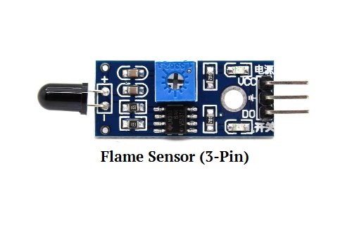
 Flame sensors are available in the market in two types one having three pins and the other having four pins respectively. Both of the sensors can be easily interfaced with any micro-controller. I am using the three-pin flame sensor in this tutorial.

Note: If you are using a 4-Pin sensor, you need to use D0 Pin to work with this example.
A flame sensor can detect fire or any other light sources whose wavelength is in the range of 760nm to 1100nm. This device consists of an IR sensor, an LED for indication, an operational amplifier circuit, and a potentiometer. The device is sensitive to flame so when it detects the flame it turns on its LED to show an indication. The sensitivity of the flame sensor can be adjusted according to the requirements. It can be used at different places e.g. in offices, homes, institutions, industrial applications.
The PCB of this electronic circuit has a potentiometer. The Sensitivity of the Digital pin can be varied using the potentiometer.
|
|
|
Flame Sensor Interfacing with 8051
Connection
Flame Sensor
- Vcc – 5v
- GND – Ground
- DO – P1.0
LCD
- RS – P2.0
- RW – P2.1
- EN – P2.2
- Data Lines – P3.0 – P3.7

Source Code
If it is detecting any flame in front of this sensor, LCD will display “Flame Detected”.
/* Flame sensor interfacing with 8051
 * By EmbeTronicX
*/

#include<reg51.h>
#define lcd P3

sbit FLAME=P1^0;

sbit rs=P2^0; //register select
sbit rw=P2^1; //RW
sbit en=P2^2; //enable

void lcd_init();
void cmd(unsigned char);
void dat(unsigned char);
void delay();
void lcd_string(char *s);

void main()
{
    lcd_init();
    lcd_string("  EmbeTronicX   ");
    while(1) {
        if(FLAME) {
            cmd(0xc0);
            lcd_string("Flame Detected");
            delay();
        } else {
            cmd(0xc0);
            lcd_string("                ");
        }
    }
}

void lcd_init()
{
    cmd(0x38);
    cmd(0x0e);
    cmd(0x06);
    cmd(0x01);
    cmd(0x80);
}

void cmd(unsigned char a)
{
    lcd=a;
    rs=0;
    rw=0;
    en=1;
    delay();
    en=0;
}

void dat(unsigned char b)
{
    lcd=b;
    rs=1;
    rw=0;
    en=1;
    delay();
    en=0;
}

void lcd_string(char *s)
{
    while(*s) {
       dat(*s++);
     }
}

void delay()
{
    unsigned int i;
    for(i=0;i<20000;i++);
}
Note: In our tutorial, we are using the 3-pin sensor. Only Digital output is available in this sensor. If you want to use the 4-pin sensor, you can use the 4-pin sensor’s, D0 Pin. But somebody may want to use an A0 pin in a 4-pin sensor. In that case, you cannot use this example. You need to use ADC for that case since it is not digital output.
In our next tutorial, we will see how to detect the rain using 8051.
You can also read the below tutorials.
|
|
|
Embedded Software | Firmware | Linux Devic Deriver | RTOS
Hi, I am a tech blogger and an Embedded Engineer. I am always eager to learn and explore tech-related concepts. And also, I wanted to share my knowledge with everyone in a more straightforward way with easy practical examples. I strongly believe that learning by doing is more powerful than just learning by reading. I love to do experiments. If you want to help or support me on my journey, consider sharing my articles, or Buy me a Coffee! Thank you for reading my blog! Happy learning!
