In our previous tutorial, we have seen how to interface the IR sensor with 8051. In this tutorial, we are going to see GPS Interfacing with 8051.
Table of Contents
Prerequisites
Before we will start i would suggest you to read these topics. Then only you can understand this strongly. If you already know, please go ahead.
Components Required
- 8051 Development Board
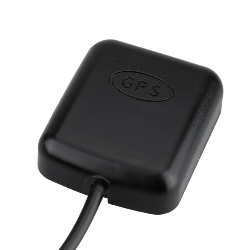
- GPS Module
- LCD Module (To print the Latitude and Longitude)
GPS
Introduction
The Global Positioning System (GPS) is a satellite-based navigation system that consists of 24 orbiting satellites, each of which makes two circuits around the Earth every 24 hours. These satellites transmit three bits of information – the satellite’s number, its position in space, and the time the information is sent. These signals are picked up by the GPS receiver, which uses this information to calculate the distance between it and the GPS satellites.

With signals from three or more satellites, a GPS receiver can triangulate its location on the ground (i.e., longitude and latitude) from the known position of the satellites. With four or more satellites, a GPS receiver can determine a 3D position (i.e., latitude, longitude, and elevation). In addition, a GPS receiver can provide data on your speed and direction of travel. Anyone with a GPS receiver can access the system. Because GPS provides real-time, three-dimensional positioning, navigation, and timing 24 hours a day, 7 days a week, all over the world, it is used in numerous applications, including GIS data collection, surveying, and mapping.
|
|
|
GPS Data Format
GPS units spit out data in a dizzying array of formats. It can become a challenge to take the output from a GPS unit.
When you connect a GPS board up, and look at the data coming off of it, you are likely to see something like this:
$GPRMC,000009.800,V,,,,,0.00,0.00,060180,,,N*43
$GPVTG,0.00,T,,M,0.00,N,0.00,K,N*32
$GPGGA,000010.800,,,,,0,0,,,M,,M,,*41
$GPGSA,A,1,,,,,,,,,,,,,,,*1E
$GPRMC,000010.800,V,,,,,0.00,0.00,060180,,,N*4B
$GPVTG,0.00,T,,M,0.00,N,0.00,K,N*32
$GPGGA,000011.800,,,,,0,0,,,M,,M,,*40
$GPGSA,A,1,,,,,,,,,,,,,,,*1E
$GPRMC,000011.800,V,,,,,0.00,0.00,060180,,,N*4A
$GPVTG,0.00,T,,M,0.00,N,0.00,K,N*32
$GPGGA,000012.800,,,,,0,0,,,M,,M,,*43
$GPGSA,A,1,,,,,,,,,,,,,,,*1E
$GPGSV,1,1,00*79
This is what the data looks like when your GPS does not have a fix. When it does have a fix, there will be all types of numbers between the commas in the lines above. So, how do we make sense of all this? The first thing is to learn some of the lingo. Each line above is referred to as a NMEA sentence. There are different NMEA sentence type, and the type is indicated by the first characters before the comma. So, $GPGSA is a certain type of NMEA sentence, and $GPRMC is a different type of NMEA sentence. To make this whole thing a manageable problem, the first thing we must realize is that the data that we want will be in the $GPRMC sentence. If your GPS unit has options to turn the other sentences off, then turn them off to simplify the data getting thrown at you. If you can not turn the other sentences off, then just ignore them, and focus on the you care about, $GPRMC.
If your GPS has a fix, then your GPS sentences should look something like this:
|
|
|
$GPRMC,092204.999,A,4250.5589,S,14718.5084,E,0.00,89.68,211200,,A*25
Lets start by breaking down the $GPRMC sentence.
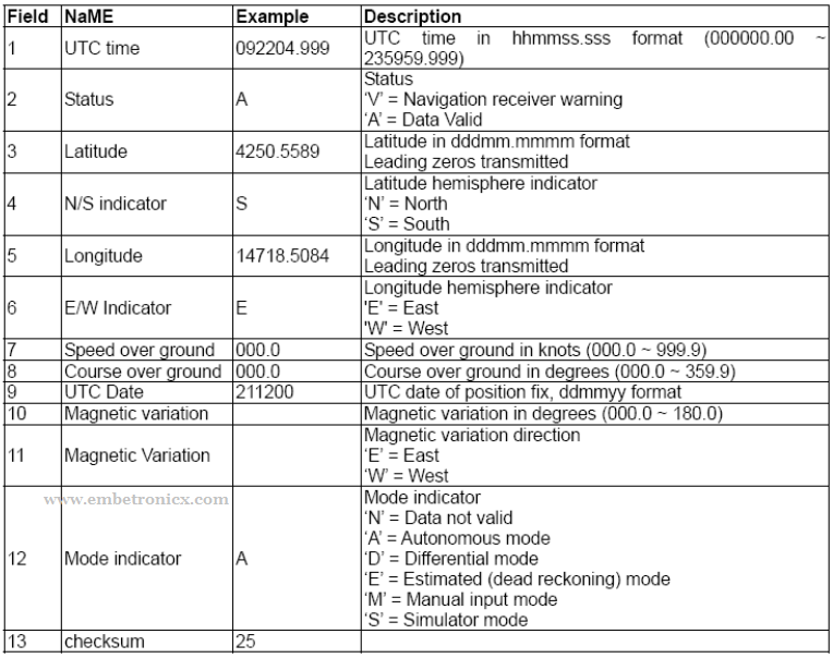
- The $GPRMC is simply telling what sentence type is on the line.
- The next number, represents the Coordinated Universal Time (UTC). It works like this, 092204.999 would be 09:22 and 04.999 seconds in UTC. Since converting from UTC to your local time is simply a matter of knowing what time zone you are in, you can see that one thing you get from a GPS is a very accurate clock.
- The next letter just lets you know if your signal is Active (A) or Void (V). An ‘A’ indicates you are getting a signal and things are working properly. A ‘V’ means you do not have a signal.
- Now, for the good stuff, the next number and following letter gives you your lattitude. 4250.5589,S should be interpreted as, Your Latitude is: 42 degrees, 50.5589 minutes, in the Southern Hemisphere.
- Similarly, the next number, 14718.5084,E, is Longitude. This is interpreted as, Your Longitude is: 147 degrees 18.5084 minutes, in the Eastern Hemisphere.
Note: Degrees could be a one, two or three digit number. Hence you have to be careful parsing this data. What is always the case is that the first two numerals to the left of the decimal place, and the numbers to the right of the decimal represent the minutes. So, always take the number starting two to the left of the decimal, and those following all the way to the comma, and that is your minutes. Unfortunately, if you simply try to put 4250.5589,S,14718.5084,E, into Google Earth, it will not recognize it. The simplest thing you can do to get Google Earth to recognize and properly display the coordinate would be to enter the following:
42 50.5589S, 147 18.5084E
|
|
|
Notice the space inserted between degrees and minutes, and no comma before hemisphere designation. This would properly display that single point via the Google Earth search bar.
This data is enough to get Latitude and Longitude.
Applications
GPS used in many fields.
- Agriculture
- Aviation
- Environment
- Marine
- Public Safety & Disaster Relief
- Rail
- Recreation
- Roads & Highways
- Space
- Surveying & Mapping
Now we will interface the GPS Module to 8051.
GPS Interfacing with 8051
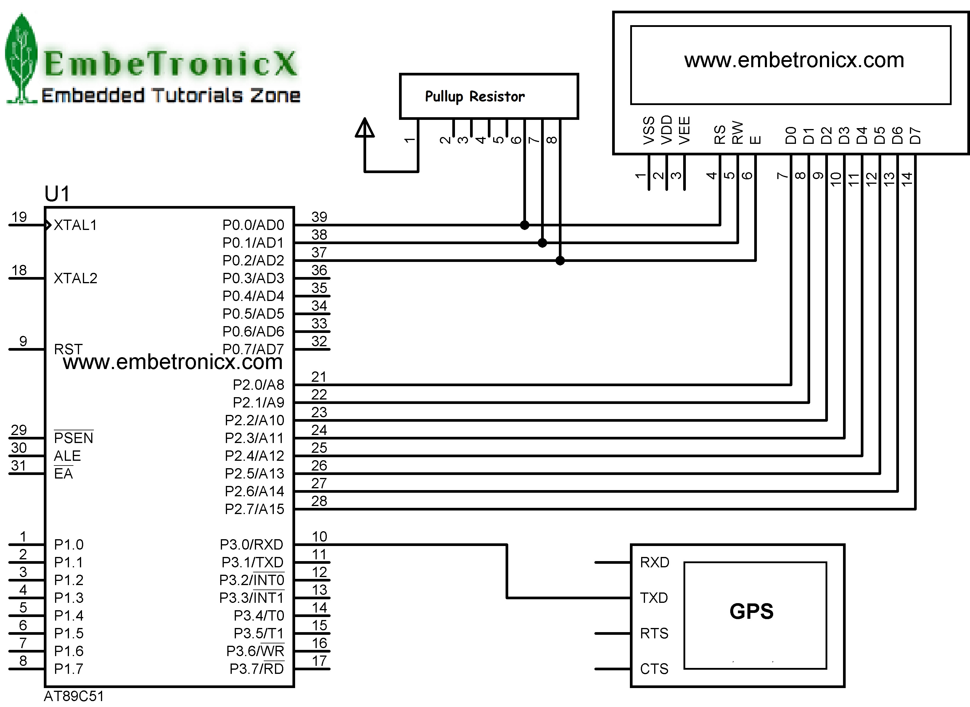
Connection
LCD:
|
|
|
- RS – P0.0
- RW – P0.1
- EN – P0.2
- Data Lines – P2.0 – P2.7
GPS:
- VCC – Power Supply 3.3 – 6 V
- GND – Ground
- TX – (P3.0) UART RX Pin
Programming – GPS Interfacing with 8051
This program will display the latitude and longitude in LCD. In this code, while loop doesn’t do anything. Everything will be done by Serial ISR function. That prints are based on Indian latitude and longitude. If you didn’t get proper digits in LCD, please separate that arrays based on your country’s lat and long. I’ve mentioned those array above.
#include<reg51.h>
#include <stdio.h>
#include <string.h>

#define lcd_data P2

sbit rs=P0^0;
sbit rw=P0^1;
sbit en=P0^2;

void lcd_init();
void cmd(unsigned char a);
void dat(unsigned char b);
void show(unsigned char *s);
void lcd_delay();

void tx(unsigned char send);
void tx_str(unsigned char *s);
unsigned char rx();

char namegps[7], name1gps[7] = "GPRMC,",gpsdat[63];
char msggps , checkgps;
int h;
unsigned char f;

void main()
{
    TMOD = 0x20;
    TH1 = TL1=0xfd;
    SCON = 0x50;
    TR1 = 1;
    IE = 0x90;
    lcd_init();
    cmd(0x80);
    show("LON:                ");
    cmd(0xc0);
    show("LAT:                ");
    while(1);
}


void ISR_sc(void) interrupt 4
{
    if(RI==1){
        msggps= rx();
        if(msggps=='$') {
            EA = 0;
            for(f=0;f<=5;f++) {
                namegps[f]=rx();
            }
            checkgps=strcmp(namegps,name1gps);
          if(checkgps==0) {
                for(f=0;f<=62;f++) {
                    gpsdat[f]=rx();
                }
                cmd(0x84);
                for(h=12;h<14;h++) {
                    dat(gpsdat[h]);
                }
                dat('.');
                for(h=14;h<16;h++) {
                    dat(gpsdat[h]);
                }
                for(h=17;h<19;h++) {
                    dat(gpsdat[h]);
                }
                dat(223);
                dat(' ');
                dat('N');

                cmd(0xc4);
                for(h=26;h<28;h++) {
                    dat(gpsdat[h]);
                }
                dat('.');
                for(h=28;h<30;h++) {
                    dat(gpsdat[h]);
                }
                for(h=31;h<33;h++) {
                    dat(gpsdat[h]);
                }
                dat(223);
                dat(' ');
                dat('E');
                EA = 1;
            }
        }
    }
}

void tx(unsigned char send)
{
    SBUF=send;
    while(TI==0);
    TI=0;
}

void tx_str(unsigned char *s)
{
    while(*s)
        tx(*s++);
}

unsigned char rx()
{
    while(RI==0);
    RI=0;
    return SBUF;
}

void lcd_init()
{
    cmd(0x38);
    cmd(0x0e);
    cmd(0x01);
    cmd(0x06);
    cmd(0x0c);
    cmd(0x80);
}

void cmd(unsigned char a)
{
    lcd_data=a;
    rs=0;
    rw=0;
    en=1;
    lcd_delay();
    en=0;
}

void dat(unsigned char b)
{
    lcd_data=b;
    rs=1;
    rw=0;
    en=1;
    lcd_delay();
    en=0;
}

void show(unsigned char *s)
{
    while(*s) {
        dat(*s++);
    }
}

void lcd_delay()
{
    unsigned int lcd_delay;
    for(lcd_delay=0;lcd_delay<=6000;lcd_delay++);
}
You can try this code with hardware. In our next tutorial, we will see how to interface the Bluetooth module with 8051.
You can also read the below tutorials.
|
|
|
Embedded Software | Firmware | Linux Devic Deriver | RTOS
Hi, I am a tech blogger and an Embedded Engineer. I am always eager to learn and explore tech-related concepts. And also, I wanted to share my knowledge with everyone in a more straightforward way with easy practical examples. I strongly believe that learning by doing is more powerful than just learning by reading. I love to do experiments. If you want to help or support me on my journey, consider sharing my articles, or Buy me a Coffee! Thank you for reading my blog! Happy learning!
