In our previous tutorial, we have interfaced the 8051 with the RFID reader. Now we will see 8051 I2C Interfacing Tutorial. so we will Interface EEPROM to check I2C.
Table of Contents
8051 I2C Interfacing Tutorial
Suggestion to read
Before getting into I2C interfacing with 8051, Please read the below topics.
Introduction
I²C
I²C is a serial computer bus, which is invented by NXP semiconductors previously it is named as Philips semiconductors. The I²C bus is used to attach low-speed peripheral integrated circuits to microcontrollers and processors. I²C bus uses two bidirectional open-drain lines such as SDA (serial data line) and SCl (serial clock line) and these are pulled up with resistors. I²C bus permits a master device to start communication with a slave device. Data is interchanged between these two devices. Typical voltages used are +3.3V or +5V although systems with extra voltages are allowed. Nowadays new microcontrollers have inbuilt I²C Registers. But in 8051 there is no such registers. So we have to achieve I²C in 8051. So in this tutorial, we will see how to achieve that.
Many devices support I²C. For example, EEPROM, ADC, LCD, etc. For the sake of implementing I²C, we are going to interface EEPROM.
EEPROM
Electrically Erasable Programmable ROM (EEPROM) is a user-modifiable ROM that can be removed and reprogrammed frequently through the application of higher than the normal electrical voltage. An EEPROM is a kind of non-volatile memory used in electronic devices like computers to store small quantities of data that should be saved when power is detached.
|
|
|
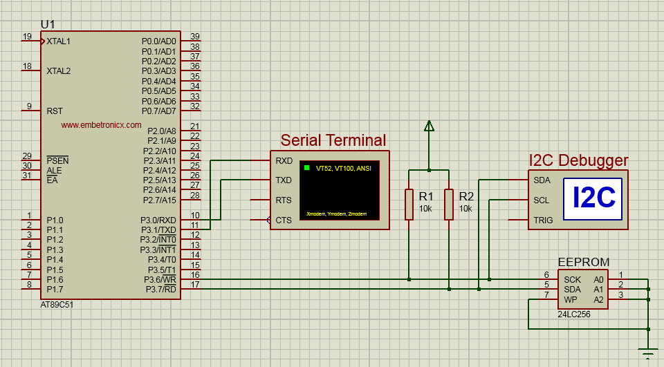
Connection Diagram
SCK – P3.6
SDA – P3.7
I²C Implementation
Write Mode
- Send the START command from the Master.
- Send Device (EEPROM) Address with write mode.
- Send Register address in Device (EEPROM), Where we have to access.
- Send the Data to the Device (EEPROM).
- If you want to send more than one byte, keep sending that byte.
- Finally, Send the STOP command.
Read Mode
- Send the START command from the Master.
- Send Device (EEPROM) Address with write mode.
- Send Register address in Device (EEPROM), Where we have to access.
- Send again START command or Repeated START command.
- Send Device address with Reading mode.
- Read the data from Device (EEPROM).
- Finally, Send the STOP command.
Code
In our code, First, we will Write the Data into EEPROM. Then we will read that data from EEPROM and send it to Serial Communication (UART). So it will print in the serial console.
START Command
 Just go through the above diagram. In this
|
|
|
- Initially, SDA and SCL are High.
- SDA first goes to Zero.
- Then SCL goes to Zero.
This is the START condition. Look at the below code.
void i2c_start(void)
{
	SDA=1;
	SCL=1;
	SDA=0;
	SCL=0;
}
STOP Command
When SCL is High, We have to toggle the SDA Low to High.
void i2c_stop(void)
{
	SDA=0;
	SCL=1;
	SDA=1;
	SCL=0;
}
Send Data
Sending Data and addresses are the same procedure. Here we have to send bit by bit to the SDA based on the SCL.
void i2c_send (unsigned char send)
{
	unsigned char i;
	EP_DATA=send;
	for(i=0;i<=7;i++)
	{
		SDA=msb;
		SCL=1;
		SCL=0;
		EP_DATA=EP_DATA<<1;
	}
	while(SDA!=0);
	SCL=1;
	SCL=0;

}
Read Data
Reading also the same as write data. We have to read bit by bit from the SDA line based on SCL. Go through the Full code and try it.
|
|
|
Full Code
#include <reg51.h>

unsigned char bdata EP_DATA;

sbit lsb=EP_DATA^0;
sbit msb=EP_DATA^7;

sbit SDA = 	P3^7;
sbit SCL = 	P3^6;

unsigned char rec[12];

void i2c_start(void);
void i2c_stop(void);

void i2c_send (unsigned char);
void i2c_send_byte(unsigned char addr,unsigned char dataa);
void i2c_send_string(unsigned char addr,unsigned char *s);

unsigned char i2c_read(void);
unsigned char i2c_read_byte(unsigned char addr);
unsigned char i2c_read_string(unsigned char addr);

void ser_init();
void tx(unsigned char send);
void tx_str(unsigned char *s);

void i2c_start(void)
{
	SDA=1;
	SCL=1;
	SDA=0;
	SCL=0;
}


void i2c_send (unsigned char send)
{
	unsigned char i;
	EP_DATA=send;
	for(i=0;i<=7;i++) {
		SDA=msb;
		SCL=1;
		SCL=0;
		EP_DATA=EP_DATA<<1;
	}
	while(SDA!=0);
	SCL=1;
	SCL=0;
}

unsigned char i2c_read(void)
{
	unsigned char i;
	lsb=SDA;
	for(i=0;i<=7;i++) {
		EP_DATA=EP_DATA<<1;
		lsb=SDA;
		SCL=1;
		SCL=0;
	}

	if(EP_DATA==13) {
		SDA=1;
		SCL=1;
		SCL=0;
		SDA=0;
		i2c_stop();
		return(EP_DATA);
	}

	SDA=0;
	SCL=1;
	SCL=0;
	SDA=1;

	return(EP_DATA);
}

void i2c_stop(void)
{
	SDA=0;
	SCL=1;
	SDA=1;
	SCL=0;
}

void i2c_send_byte(unsigned char addr,unsigned char dataa)
{
	i2c_start();
	i2c_send(0xa0);
	i2c_send(addr);
	i2c_send(dataa);
	i2c_stop();
}

unsigned char i2c_read_byte(unsigned char addr)
{
	unsigned char rec;
	i2c_start();
	i2c_send(0xa0);
	i2c_send(addr);
	i2c_start();
	i2c_send(0xa1);
	rec=i2c_read();
	i2c_stop();
	return rec;
}

void i2c_send_string(unsigned char addr,unsigned char *s)
{
	i2c_start();
	i2c_send(0xa0);
	i2c_send(addr);
	while(*s) {
		i2c_send(*s++);
	}
	i2c_stop();
}

unsigned char i2c_read_string(unsigned char addr)
{
	unsigned char i;
	i2c_start();
	i2c_send(0xa0);
	i2c_send(addr);
	i2c_start();
	i2c_send(0xa1);
	for(i=0;i<10;i++) {
	rec[i]=i2c_read();	}
	i2c_stop();
	return rec;
}

void ser_init()
{
	SCON=0x50;
	TMOD|=0x20;
	TH1=0xFD;
	TL1=0xFD;
	TR1=1;
}

void tx(unsigned char send)
{
	SBUF=send;
	while(TI==0);
	TI=0;
}

void tx_str(unsigned char *s)
{
	while(*s)
		tx(*s++);
}

int main()
{
	unsigned char data[12];
	ser_init();
	i2c_send_string(0x00,"EmbeTronicX");
	i2c_read_string(0x00);
	tx_str(rec);
	while(1);
}
In our next tutorial, we will see how to interface RTC (DS1307) with 8051.
You can also read the below tutorials.
Embedded Software | Firmware | Linux Devic Deriver | RTOS
Hi, I am a tech blogger and an Embedded Engineer. I am always eager to learn and explore tech-related concepts. And also, I wanted to share my knowledge with everyone in a more straightforward way with easy practical examples. I strongly believe that learning by doing is more powerful than just learning by reading. I love to do experiments. If you want to help or support me on my journey, consider sharing my articles, or Buy me a Coffee! Thank you for reading my blog! Happy learning!
