Table of Contents
Accident Detection And Alerting System Using 8051 Microcontroller
Abstract
This project is Accident Detection And Alerting System Using 8051 Microcontroller. When an individual riding his/her bike, meets with an accident, there is a chance that the individual may suffer from a serious injury or expire instantaneously and there is no one around to help him. Well, this system is a solution to the problem. The system acts as an accident identification system that gathers and sends this vehicle information that met with an accident and conveys it to the nearest control room.
For this, the user vehicle is fixed with a GSM module and vibration sensor along with a microcontroller. Whenever a user vehicle meets with an accident, the vibration sensor detects and gives its output. This output is then detected by the microcontroller. Now the microcontroller sends this change detection signal to a GSM Module. GSM Module begins sending the accident data by SMS. We can give anyone’s a number. for example police number, ambulance number, doctor number, etc. Here we are also using LCD Module. This displays the status. Whenever an accident happens buzzer will activate.
Components Required
- 8051 Development board
- LCD Module
- GSM Module
- Vibration Sensor
- Buzzer
Software Required
- Keil IDE
Suggest to Read
Before seeing the code, first, you can see the basic interfacing tutorials of these components.
Block Diagram
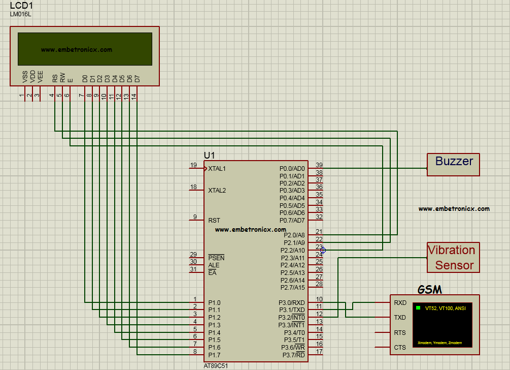
Circuit Diagram
LCD:
|
|
|
- RS – P2.0
- RW – P2.1
- EN – P2.2
- Data lines – P1
Buzzer:
- Ground Terminal – P0.0
Vibration Sensor:
- Output Pin – P3.3
GSM:
- GSM RX – P3.1
- GSM TX – P3.0
Code
If you want to download the full project, please visit Here.
|
|
|
Main.c
#include<reg51.h>
#include"GSM.h"
#include"LCD.h"

#define NUMBER1 "9876543210"   //Enter the mobile number
#define NUMBER2 "0123456789"
#define NUMBER3 "1111111111"

sbit vib = P3^2;
sbit buzzer = P0^0;

void main()
{
    unsigned int r;
    init_serial();
    LCD_initialise();
    comwrt(0x80);
    display("INITIALISING....");
    for(r=0;r<60000;r++);
    comwrt(0x80);
    display("GSM ACCIDENT DET");
    comwrt(0xC0);
    display(" VIBRATION: NO  ");
    buzzer=1;
    while(1) {
        if(vib==1) {
            buzzer=0;
            comwrt(0x80);
            display("VIBRATION DETECT");
            comwrt(0xC0);
            display(" VIBRATION: YES ");
            for(r=0;r<30000;r++);
            for(r=0;r<30000;r++);
            comwrt(0x80);
            display("SENDING MSG.....");
            sendSMS(NUMBER1,"ACCIDENT DETECTED");
            sendSMS(NUMBER2,"ACCIDENT DETECTED");
            sendSMS(NUMBER3,"ACCIDENT DETECTED");
            comwrt(0xC0);
            display("    MSG SENT    ");
            for(r=0;r<30000;r++);
            for(r=0;r<30000;r++);
            for(r=0;r<30000;r++);
            comwrt(0x80);
            display("CALLING.........");
            call(NUMBER1);
            call(NUMBER2);
            call(NUMBER3);
            comwrt(0x80);
            display("GSM ACCIDENT DET");

        }
        else
        {
            buzzer=1;
            comwrt(0xC0);
            display(" VIBRATION: NO  ");
        }

    }
}
LCD.H
#define LCDDATA P1
#define DELAY for(i=0;i<1200;i++)

sbit RS = P2^0;
sbit RW = P2^1;
sbit EN = P2^2;

void comwrt(unsigned char);
void datawrt(unsigned char);
void  LCD_initialise();
void display(unsigned char *str);

void LCD_initialise()
{
    unsigned int i,j;
    int com[5]={0x38,0x0C,0x01,0x06,0x80};
    for(j=0;j<=4;j++) {
    comwrt(com[j]);
    DELAY;
    }
}

void comwrt(unsigned char dat)
{
    unsigned int i;
    LCDDATA=dat;
    RS = 0;
    RW = 0;
    EN = 1;
    DELAY;
    EN = 0;
}

void datawrt(unsigned char dat)
{
    unsigned int i;
    LCDDATA=dat;
    RS = 1;
    RW = 0;
    EN = 1;
    DELAY;
    EN = 0;
}

void display(unsigned char *str)
{
    int i;
    for(;*str!=0;str++) {
    datawrt(*str);
    DELAY;
    }
}
GSM.H
code unsigned char SMS1[2] = "AT" ;
code unsigned char SMS2[9] = "AT+CMGF=1" ;
code unsigned char SMS3[8]= "AT+CMGS=" ; // send "
code unsigned char SMS4[3]= "ATD" ; // send "
code unsigned char SMS5[3]= "ATH" ; // send "


void sendSMS(unsigned char *num , unsigned char *msg);
void delay1(unsigned int tim);
void sendserial(unsigned char mydata1);
void call(unsigned char *num1);

unsigned char i;

void sendSMS(unsigned char *num , unsigned char *msg)
{
    for (i=0;i<2;i++)
    sendserial(SMS1[i]);
    sendserial(0X0D);
    delay1(60);

    for (i=0;i<9;i++)
    sendserial(SMS2[i]);
    sendserial(0X0D);
    delay1(60);

    for (i=0;i<8;i++)
    sendserial(SMS3[i]);
    sendserial(0x22);  // "

    for(;*num!=0;num++)
    sendserial(*num);
    sendserial(0x22);  // "
    sendserial(0X0D);
    delay1(60);

    for(;*msg!=0;msg++)
    sendserial(*msg);
    sendserial(0X1A);
    delay1(80);

}

void call(unsigned char *num1)
{
    for (i=0;i<2;i++)
    sendserial(SMS1[i]);
    sendserial(0X0D);
    delay1(60);

    for (i=0;i<9;i++)
    sendserial(SMS2[i]);
    sendserial(0X0D);
    delay1(60);

    for (i=0;i<3;i++)
    sendserial(SMS4[i]);

    for(;*num1!=0;num1++)
    sendserial(*num1);
    sendserial(0x3b);
    sendserial(0X0D);
    delay1(80);
    delay1(600);

    for (i=0;i<3;i++)
    sendserial(SMS5[i]);
    delay1(80);
}

void delay1(unsigned int tim)
{
    unsigned int h;
    for(h=0;h<=tim;h++) {
        TMOD=0X21;
        TH0=0x4B;
        TL0=0xFD;
        TR0=1;
        while(TF0==0);
        TF0=0;
    }
}

void sendserial(unsigned char mydata1)
{
    TI=0;
    SBUF= mydata1;
    while(TI==0);
}

void init_serial()
{
    SCON=0x50;
    TMOD=0x21;
    TH1=0xFD;
    TL1=0xFD;
    TR1=1;
}
Explanation
- The vibration sensor continuously checking the vibration.
- If any vibration, it will give the signal to the Microcontroller.
- Then Microcontroller Activates the Buzzer.
- Then Display the status in LCD Module.
- Then Microcontroller sends the message to the given number.
- And also it will call to that numbers.
Please read the other 8051 projects here.
|
|
|
You can also read the below tutorials.

Embedded Software | Firmware | Linux Devic Deriver | RTOS
Hi, I am a tech blogger and an Embedded Engineer. I am always eager to learn and explore tech-related concepts. And also, I wanted to share my knowledge with everyone in a more straightforward way with easy practical examples. I strongly believe that learning by doing is more powerful than just learning by reading. I love to do experiments. If you want to help or support me on my journey, consider sharing my articles, or Buy me a Coffee! Thank you for reading my blog! Happy learning!


