This article is a continuation of the Series on Linux Device Drivers and carries the discussion on Linux device drivers and their implementation. The aim of this series is to provide easy and practical examples that anyone can understand. This is the I2C Linux Device Driver using Raspberry PI – Linux Device Driver Tutorial Part 37.
We are using the Raspberry PI 4 Model B for this demonstration.
You can also read BMP280 Bosch Pressure Sensor I2C Device Driver, I2C dummy bus driver, I2C bus driver, SSD1306 driver, and GPIO Linux Driver.
Table of Contents
I2C Linux Device Driver
Prerequisites
Hardware Required
- Raspberry Pi
- SSD1306 OLED I2C Display
Bring up Raspberry PI
- Install Raspberry Pi OS (32-bit) with desktop in the SD card.
- Then install the kernel header using
sudo apt install raspberrypi-kernel-headers
For your information, In our Raspberry PI 4 board, kernel 5.4.51-v7l+ is installed.
Please enable the I2C in the Raspberry Pi.
|
|
|
I2C
I assume that you know about the I2C and how the master and slave are communicating normally. If you don’t know about I2C, please go through the I2C’s part 1 and part 2 tutorials before beginning. In this tutorial, we will focus on how the Linux kernel is handling the I2C.
I2C Subsystem
The kernel divided the I2C subsystem by Buses and Devices. The Buses are again divided into Algorithms and Adapters. The devices are again divided into Drivers and Clients. The below image will give you some understandings.
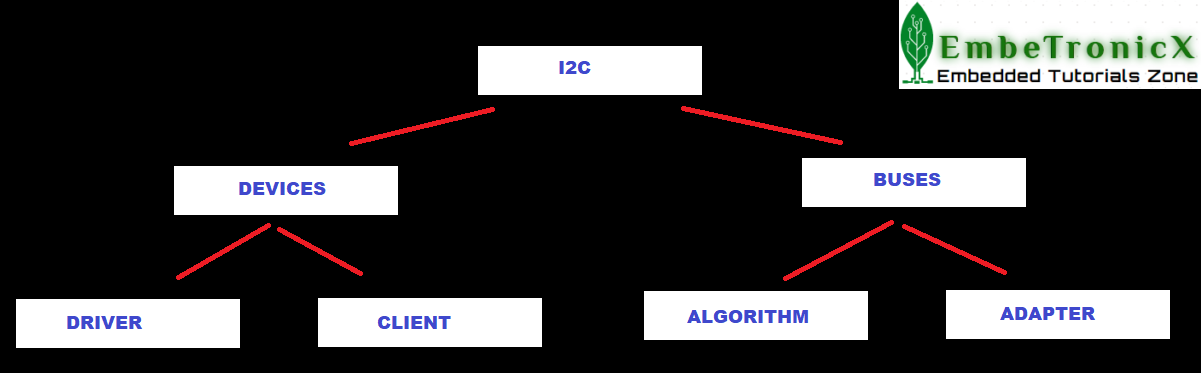
Algorithm
An Algorithm driver contains a general code that can be used for a whole class of I2C adapters.
Adapters
An Adapter effectively represents a bus – it is used to tie up a particular I2C with an algorithm and bus number. Each specific adapter driver either depends on one algorithm driver or includes its own implementation.
Clients
A Client represents a chip (slave) on the I2C.
|
|
|
Drivers
This is the driver that we are writing for the client.
Usually, Driver and Client are more closely integrated than Algorithm and Adapter.
So, you will need a driver for your I2C bus, and drivers for your I2C devices (usually one driver for each device).
I2C Driver in Linux Kernel
Steps that involve while writing the I2C device driver are given below.
- Get the I2C adapter.
- Create the
oled_i2c_board_infostructure and create a device using that. - Create the
i2c_device_idfor your slave device and register that. - Create the
i2c_driverstructure and add that to the I2C subsystem. - Now the driver is ready. So you can transfer the data between master and slave.
- Once you are done, then remove the device.
Get the I2C adapter
In raspberry Pi 4, the i2c-1 bus is available already. You can check that using the command ls -al /sys/bus/i2c/devices/. So we will use the below API to get the adapter structure of this I2C bus.
|
|
|
|
Where,
It returns the |
Create the board info
Once you get the adapter structure, then create the board info and using that board info, create the device.
|
|
|
Create Board info
Just create the i2c_board_info structure and assign required members of that.
struct i2c_board_info {
  char type[I2C_NAME_SIZE];
  unsigned short flags;
  unsigned short addr;
  void * platform_data;
  struct dev_archdata * archdata;
  struct device_node * of_node;
  struct fwnode_handle * fwnode;
  int irq;
};
where,
type[I2C_NAME_SIZE] – chip type, to initialize i2c_client.name
flags – to initialize i2c_client.flags
addr – stored in i2c_client.addr
platform_data – stored in i2c_client.dev.platform_data
archdata – copied into i2c_client.dev.archdata
of_node – pointer to OpenFirmware device node
fwnode – device node supplied by the platform firmware
irq – stored in i2c_client.irq
You can use I2C_BOARD_INFO macro to initialize the essential fields of struct i2c_board_info.
I2C_BOARD_INFO ( dev_type, dev_addr);
where,
|
Create Device
Now board info structure is ready. Let’s instantiate the device from that I2C bus.
|
where,
This will return the |
Note: If you are using the newer kernel (5.2 =<), then you must use the i2c_new_client_device API instead of i2c_new_device.
Now we will see the example for this section. So that you will get some idea that how we are using this in our code.
Example
#define I2C_BUS_AVAILABLE   (          1 )              // I2C Bus available in our Raspberry Pi
#define SLAVE_DEVICE_NAME   ( "ETX_OLED" )              // Device and Driver Name
#define SSD1306_SLAVE_ADDR  (       0x3C )              // SSD1306 OLED Slave Address

static struct i2c_adapter *etx_i2c_adapter     = NULL;  // I2C Adapter Structure
static struct i2c_client  *etx_i2c_client_oled = NULL;  // I2C Cient Structure (In our case it is OLED)

/*
** I2C Board Info strucutre
*/
static struct i2c_board_info oled_i2c_board_info = {
        I2C_BOARD_INFO(SLAVE_DEVICE_NAME, SSD1306_SLAVE_ADDR)
    };

/*
** Module Init function
*/
static int __init etx_driver_init(void)
{
    ....

    etx_i2c_adapter     = i2c_get_adapter(I2C_BUS_AVAILABLE);
    etx_i2c_client_oled = i2c_new_device(etx_i2c_adapter, &oled_i2c_board_info);

    ....
    return 0;
}
Create the device id and register
Now we have to create the i2c driver for our slave. In order to do that, you have to create the device id and i2c_driver. Then add that driver to the I2C subsystem.
|
|
|
Create the device id
Just create the structure i2c_device_id and initialize the necessary members.
struct i2c_device_id {
  char name[I2C_NAME_SIZE];
  kernel_ulong_t driver_data;
};
where,
name – Slave name
driver_data – Data private to the driver (This data will be passed to the respective driver)
After this, call MODULE_DEVICE_TABLE(i2c, my_id_table) in order to expose the driver along with its I2C device table IDs to userspace.
Create the i2c_driver
struct i2c_driver {
  unsigned int class;
  int (* attach_adapter) (struct i2c_adapter *);
  int (* probe) (struct i2c_client *, const struct i2c_device_id *);
  int (* remove) (struct i2c_client *);
  void (* shutdown) (struct i2c_client *);
  void (* alert) (struct i2c_client *, unsigned int data);
  int (* command) (struct i2c_client *client, unsigned int cmd, void *arg);
  struct device_driver driver;
  const struct i2c_device_id * id_table;
  int (* detect) (struct i2c_client *, struct i2c_board_info *);
  const unsigned short * address_list;
  struct list_head clients;
};
Where,
|
|
|
class – What kind of i2c device we instantiate (for detect)
attach_adapter – Callback for bus addition (deprecated)
probe – Callback for device binding
remove – Callback for device unbinding
shutdown – Callback for device shutdown
alert – Alert callback, for example for the SMBus alert protocol
command – Callback for bus-wide signaling (optional)
driver – Device driver model driver
id_table – List of I2C devices supported by this driver
detect – Callback for device detection
address_list – The I2C addresses to probe (for detect)
clients – List of detected clients we created (for i2c-core use only)
Add the I2C driver to the I2C subsystem
Now we have the i2c_driver structure. So we can add this structure to the I2C subsystem using the below API.
|
Where,
|
During the call to i2c_add_driver to register the I2C driver, all the I2C devices will be traversed. Once matched, the probe function of the driver will be executed.
|
|
|
You can remove the driver using i2c_del_driver(struct i2c_driver *i2c_drive).
Let’s put this together and the code snippet is shown below.
Example
/*
** This function getting called when the slave has been found
** Note : This will be called only once when we load the driver.
*/
static int etx_oled_probe(struct i2c_client *client,
                         const struct i2c_device_id *id)
{
    ...

    return 0;
}

/*
** This function getting called when the slave has been removed
** Note : This will be called only once when we unload the driver.
*/
static int etx_oled_remove(struct i2c_client *client)
{
    ...
    return 0;
}

/*
** Structure that has slave device id
*/
static const struct i2c_device_id etx_oled_id[] = {
        { SLAVE_DEVICE_NAME, 0 },
        { }
};
MODULE_DEVICE_TABLE(i2c, etx_oled_id);

/*
** I2C driver Structure that has to be added to linux
*/
static struct i2c_driver etx_oled_driver = {
        .driver = {
            .name   = SLAVE_DEVICE_NAME,
            .owner  = THIS_MODULE,
        },
        .probe          = etx_oled_probe,
        .remove         = etx_oled_remove,
        .id_table       = etx_oled_id,
};

/*
** Module Init function
*/
static int __init etx_driver_init(void)
{
    ...
    i2c_add_driver(&etx_oled_driver);
    ...
    return 0;
}
Transfer data
Till this point, everything is on our plate. So, we can start the communication between master and slave. I meant data transfer.
Send data
i2c_master_send
This API issue a single I2C message in the master transmit mode.
|
Where,
It returns negative |
i2c_smbus_write_byte
|
This API is used to send one byte to the slave.
Where,
It returning negative |
i2c_smbus_write_byte_data
|
Where,
It returning negative |
i2c_smbus_write_word_data
|
Where,
It returning negative |
i2c_smbus_write_block_data
|
Where,
It returns negative
|
Read data
i2c_master_recv
This API issue a single I2C message in master receive mode.
|
Where,
It returns negative
|
i2c_smbus_read_byte
|
Where, It is returning negative |
i2c_smbus_read_byte_data
|
Where,
It is returning negative |
i2c_smbus_read_word_data
|
Where,
This returns negative
|
i2c_smbus_read_block_data
|
Where,
This returns negative Note that using this function requires that the client’s adapter support the |
i2c_transfer
If you want to send multiple I2C messages then you can use the below-given API.
|
|
|
|
Where,
It returns negative |
How I2C bus driver works
- I2C client driver initiates transfer using a function like
i2c_transfer, - It comes to the
master_xferfunction in the bus driver (drivers/i2c/busses/*). - The bus driver splits the entire transaction into START, STOP, ADDRESS, READ with ACK, READ with NACK, etc. These conditions have to be created on the real i2c bus. The bus driver writes to the I2C hardware adaptor to generate these conditions on the I2C bus one by one, sleeping on a wait queue in between (basically giving the CPU to some other task to do some useful job rather than polling until hardware finishes).
- Once the hardware has finished a transaction on the bus (for eg a START condition), an interrupt will be generated and the ISR will wake up the sleeping
master_xfer. - Once
master_xferwakes up, he will go and advise the hardware adaptor to send the second condition (for eg ADDRESS of the chip). - This continues till the whole transaction is over and return back to the client driver.
The point to note here is sleep done by the thread in between each condition. This is why I2C transactions cannot be used in ISRs. For client driver, it is just a simple function like i2c_transfer, i2c_master_send. But it is implemented in the bus driver as explained above.
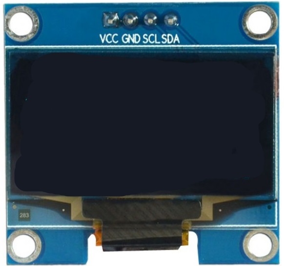
SSD1306 OLED
SSD1306 is a single-chip CMOS OLED/PLED driver with a controller for an organic / polymer light-emitting diode dot-matrix graphic display system. It consists of 128 segments and 64commons.
|
|
|
The SSD1306 embeds with contrast control, display RAM, and oscillator, which reduces the number of external components and power consumption. It has 256-step brightness control. Data/Commands are sent from general MCU through the hardware selectable 6800/8000 series compatible Parallel Interface, I2C interface, or Serial Peripheral Interface. It is suitable for many compact portable applications, such as mobile phone sub-display, MP3 player and calculator, etc.
The operating voltage of the SSD1306 controller is from 1.65V to 3.3V while the OLED panel requires 7V to 15V supply voltage. All these different power requirements are sufficed using internal charge pump circuitry. This makes it possible to connect it to any 5V logic microcontroller easily without using any logic level converter.
SSD1306 OLED Memory Map
Regardless of the size of the OLED module, the SSD1306 driver has a built-in 1KB Graphic Display Data RAM (GDDRAM) for the screen which holds the bit pattern to be displayed. This 1K memory area is organized in 8 pages (from 0 to 7). Each page contains 128 columns/segments (block 0 to 127). And each column can store 8 bits of data (from 0 to 7). That surely tells us we have
8 pages x 128 segments x 8 bits of data = 8192 bits = 1024 bytes = 1KB memory
Here are the complete specifications:
| Display Technology | OLED (Organic LED) |
| MCU Interface | I2C / SPI |
| Screen Size | 0.96 Inch Across |
| Resolution | 128×64 pixels |
| Operating Voltage | 3.3V – 5V |
| Operating Current | 20mA max |
| Viewing Angle | 160° |
| Characters Per Row | 21 |
| Number of Character Rows | 7 |
Data in SSD1306 OLED
There are two types of data that we can send to the SSD1306 OLED.
- Command
- Data to be written into the GDDRAM
Whenever you send some data, you have to send the control byte first, then send the data byte after that. That control byte used to tell the data that you are sending is command or data.
Control Byte
| Bit 7 | Bit 6 | Bit 5 | Bit 4 | Bit 3 | Bit 2 | Bit 1 | Bit 0 |
| Co bit * | D/C * | 0 | 0 | 0 | 0 | 0 | 0 |
The first 6 bits should be 0.
D/C – If this bit is 1, then the next byte will be a command. If this bit is 0, then the next byte will be data.
|
|
|
Co – If this bit is 0, then the following bytes contain data bytes only.
Example
If you want to send a command, make the control byte as 0x00 and attach the command to the next byte. Let’s say I want to send the command 0xAE (Turn OFF the display), Follow the below steps.
- Send the Start condition
- Send the Slave address with R/W bit
- Send the Control Byte (0x00)
- Send the Command byte (0xAE)
- Send the Stop condition
If you want to write some 0xFF to the display, then follow the below steps.
- Send the Start condition
- Send the Slave address with R/W bit
- Send the Control Byte (0x40)
- Send the Command byte (0xFF)
- Send the Stop condition
For more information, please refer to the datasheet of the SSED1306.
Example Programming
In this example, we are going to use the SSD1306 OLED display as the slave device. This is not the tutorial of SSD1306 whereas this is the tutorial of I2C in the Linux device driver. So we don’t show any circus in the SSD1306 OLED display. We will just fill something in the display and clear that. That’s all.
|
|
|
Note: Don’t care about the commands that we send to initialize the OLED display. We will explain that in separate tutorials.
The concept of this example is, we will fill 0xFF in the full display when we load the driver and clears it while unloading. This makes the process simple right. Let’s do it.
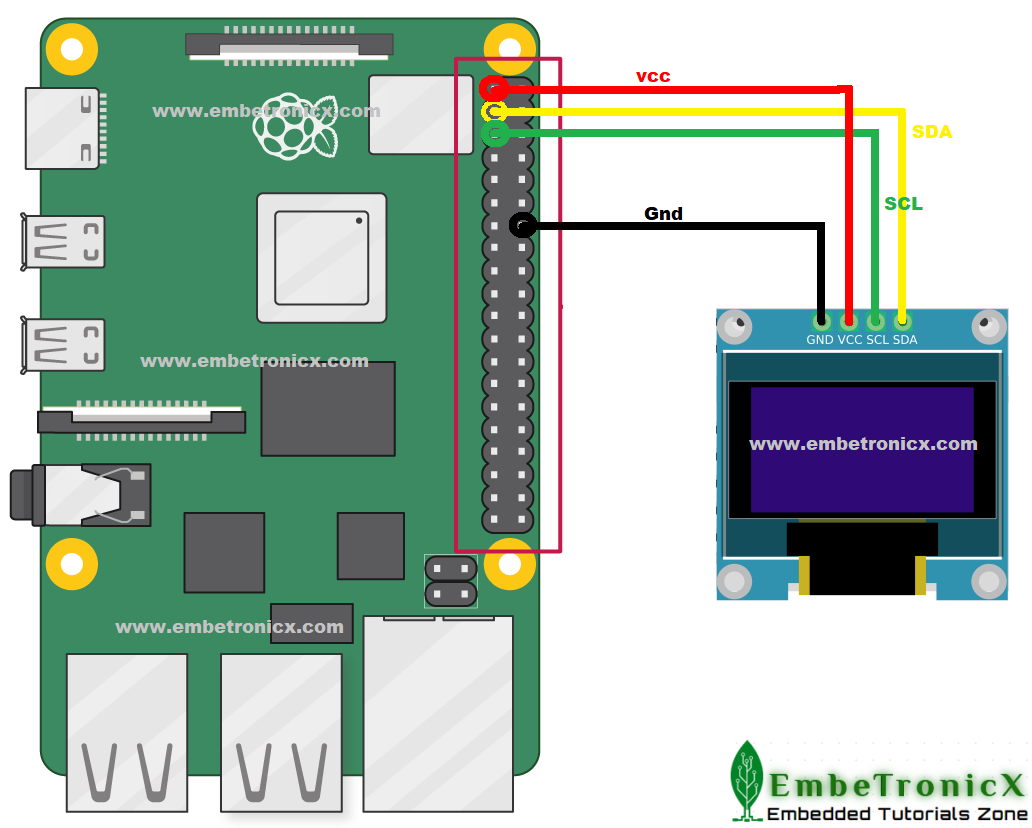
Please enable the I2C in the Raspberry Pi.
If you see the Pinout of the Raspberry Pi 4,
- GPIO 2 – SDA
- GPIO 3 – SCL
Connection Diagram
|
|
|
Driver Source Code
If you want to interface any other I2C slave, then you don’t care about the functions that start with SSD1306_. You implement your own functions for that slave.
[Get the source code from the GitHub]
/***************************************************************************//**
*  \file       driver.c
*
*  \details    Simple I2C driver explanation (SSD_1306 OLED Display Interface)
*
*  \author     EmbeTronicX
*
*  \Tested with Linux raspberrypi 5.4.51-v7l+
*
* *******************************************************************************/
#include <linux/module.h>
#include <linux/init.h>
#include <linux/slab.h>
#include <linux/i2c.h>
#include <linux/delay.h>
#include <linux/kernel.h>

#define I2C_BUS_AVAILABLE   (          1 )              // I2C Bus available in our Raspberry Pi
#define SLAVE_DEVICE_NAME   ( "ETX_OLED" )              // Device and Driver Name
#define SSD1306_SLAVE_ADDR  (       0x3C )              // SSD1306 OLED Slave Address

static struct i2c_adapter *etx_i2c_adapter     = NULL;  // I2C Adapter Structure
static struct i2c_client  *etx_i2c_client_oled = NULL;  // I2C Cient Structure (In our case it is OLED)

/*
** This function writes the data into the I2C client
**
**  Arguments:
**      buff -> buffer to be sent
**      len  -> Length of the data
**
*/
static int I2C_Write(unsigned char *buf, unsigned int len)
{
    /*
    ** Sending Start condition, Slave address with R/W bit,
    ** ACK/NACK and Stop condtions will be handled internally.
    */
    int ret = i2c_master_send(etx_i2c_client_oled, buf, len);

    return ret;
}

/*
** This function reads one byte of the data from the I2C client
**
**  Arguments:
**      out_buff -> buffer wherer the data to be copied
**      len      -> Length of the data to be read
**
*/
static int I2C_Read(unsigned char *out_buf, unsigned int len)
{
    /*
    ** Sending Start condition, Slave address with R/W bit,
    ** ACK/NACK and Stop condtions will be handled internally.
    */
    int ret = i2c_master_recv(etx_i2c_client_oled, out_buf, len);

    return ret;
}

/*
** This function is specific to the SSD_1306 OLED.
** This function sends the command/data to the OLED.
**
**  Arguments:
**      is_cmd -> true = command, flase = data
**      data   -> data to be written
**
*/
static void SSD1306_Write(bool is_cmd, unsigned char data)
{
    unsigned char buf[2] = {0};
    int ret;

    /*
    ** First byte is always control byte. Data is followed after that.
    **
    ** There are two types of data in SSD_1306 OLED.
    ** 1. Command
    ** 2. Data
    **
    ** Control byte decides that the next byte is, command or data.
    **
    ** -------------------------------------------------------
    ** |              Control byte's | 6th bit  |   7th bit  |
    ** |-----------------------------|----------|------------|
    ** |   Command                   |   0      |     0      |
    ** |-----------------------------|----------|------------|
    ** |   data                      |   1      |     0      |
    ** |-----------------------------|----------|------------|
    **
    ** Please refer the datasheet for more information.
    **
    */
    if( is_cmd == true )
    {
        buf[0] = 0x00;
    }
    else
    {
        buf[0] = 0x40;
    }

    buf[1] = data;

    ret = I2C_Write(buf, 2);
}


/*
** This function sends the commands that need to used to Initialize the OLED.
**
**  Arguments:
**      none
**
*/
static int SSD1306_DisplayInit(void)
{
    msleep(100);               // delay

    /*
    ** Commands to initialize the SSD_1306 OLED Display
    */
    SSD1306_Write(true, 0xAE); // Entire Display OFF
    SSD1306_Write(true, 0xD5); // Set Display Clock Divide Ratio and Oscillator Frequency
    SSD1306_Write(true, 0x80); // Default Setting for Display Clock Divide Ratio and Oscillator Frequency that is recommended
    SSD1306_Write(true, 0xA8); // Set Multiplex Ratio
    SSD1306_Write(true, 0x3F); // 64 COM lines
    SSD1306_Write(true, 0xD3); // Set display offset
    SSD1306_Write(true, 0x00); // 0 offset
    SSD1306_Write(true, 0x40); // Set first line as the start line of the display
    SSD1306_Write(true, 0x8D); // Charge pump
    SSD1306_Write(true, 0x14); // Enable charge dump during display on
    SSD1306_Write(true, 0x20); // Set memory addressing mode
    SSD1306_Write(true, 0x00); // Horizontal addressing mode
    SSD1306_Write(true, 0xA1); // Set segment remap with column address 127 mapped to segment 0
    SSD1306_Write(true, 0xC8); // Set com output scan direction, scan from com63 to com 0
    SSD1306_Write(true, 0xDA); // Set com pins hardware configuration
    SSD1306_Write(true, 0x12); // Alternative com pin configuration, disable com left/right remap
    SSD1306_Write(true, 0x81); // Set contrast control
    SSD1306_Write(true, 0x80); // Set Contrast to 128
    SSD1306_Write(true, 0xD9); // Set pre-charge period
    SSD1306_Write(true, 0xF1); // Phase 1 period of 15 DCLK, Phase 2 period of 1 DCLK
    SSD1306_Write(true, 0xDB); // Set Vcomh deselect level
    SSD1306_Write(true, 0x20); // Vcomh deselect level ~ 0.77 Vcc
    SSD1306_Write(true, 0xA4); // Entire display ON, resume to RAM content display
    SSD1306_Write(true, 0xA6); // Set Display in Normal Mode, 1 = ON, 0 = OFF
    SSD1306_Write(true, 0x2E); // Deactivate scroll
    SSD1306_Write(true, 0xAF); // Display ON in normal mode

    return 0;
}

/*
** This function Fills the complete OLED with this data byte.
**
**  Arguments:
**      data  -> Data to be filled in the OLED
**
*/
static void SSD1306_Fill(unsigned char data)
{
    unsigned int total  = 128 * 8;  // 8 pages x 128 segments x 8 bits of data
    unsigned int i      = 0;

    //Fill the Display
    for(i = 0; i < total; i++)
    {
        SSD1306_Write(false, data);
    }
}

/*
** This function getting called when the slave has been found
** Note : This will be called only once when we load the driver.
*/
static int etx_oled_probe(struct i2c_client *client,
                         const struct i2c_device_id *id)
{
    SSD1306_DisplayInit();

    //fill the OLED with this data
    SSD1306_Fill(0xFF);

    pr_info("OLED Probed!!!\n");

    return 0;
}

/*
** This function getting called when the slave has been removed
** Note : This will be called only once when we unload the driver.
*/
static int etx_oled_remove(struct i2c_client *client)
{
    //fill the OLED with this data
    SSD1306_Fill(0x00);

    pr_info("OLED Removed!!!\n");
    return 0;
}

/*
** Structure that has slave device id
*/
static const struct i2c_device_id etx_oled_id[] = {
        { SLAVE_DEVICE_NAME, 0 },
        { }
};
MODULE_DEVICE_TABLE(i2c, etx_oled_id);

/*
** I2C driver Structure that has to be added to linux
*/
static struct i2c_driver etx_oled_driver = {
        .driver = {
            .name   = SLAVE_DEVICE_NAME,
            .owner  = THIS_MODULE,
        },
        .probe          = etx_oled_probe,
        .remove         = etx_oled_remove,
        .id_table       = etx_oled_id,
};

/*
** I2C Board Info strucutre
*/
static struct i2c_board_info oled_i2c_board_info = {
        I2C_BOARD_INFO(SLAVE_DEVICE_NAME, SSD1306_SLAVE_ADDR)
    };

/*
** Module Init function
*/
static int __init etx_driver_init(void)
{
    int ret = -1;
    etx_i2c_adapter     = i2c_get_adapter(I2C_BUS_AVAILABLE);

    if( etx_i2c_adapter != NULL )
    {
        etx_i2c_client_oled = i2c_new_device(etx_i2c_adapter, &oled_i2c_board_info);

        if( etx_i2c_client_oled != NULL )
        {
            i2c_add_driver(&etx_oled_driver);
            ret = 0;
        }

        i2c_put_adapter(etx_i2c_adapter);
    }

    pr_info("Driver Added!!!\n");
    return ret;
}

/*
** Module Exit function
*/
static void __exit etx_driver_exit(void)
{
    i2c_unregister_device(etx_i2c_client_oled);
    i2c_del_driver(&etx_oled_driver);
    pr_info("Driver Removed!!!\n");
}

module_init(etx_driver_init);
module_exit(etx_driver_exit);

MODULE_LICENSE("GPL");
MODULE_AUTHOR("EmbeTronicX <[email protected]>");
MODULE_DESCRIPTION("Simple I2C driver explanation (SSD_1306 OLED Display Interface)");
MODULE_VERSION("1.34");
Makefile
obj-m += driver.o

KDIR = /lib/modules/$(shell uname -r)/build


all:
    make -C $(KDIR)  M=$(shell pwd) modules

clean:
    make -C $(KDIR)  M=$(shell pwd) clean
Testing the Device Driver
- Build the driver by using Makefile (
sudo make) - Load the driver using
sudo insmod driver.ko - See the Display is filled.
- Unload the driver using
sudo rmmod driver - See the Display has been cleared
Output Video
Click here if you don’t see the output gif
 In our next tutorial, we will discuss the dummy I2C bus driver.
Please find the other Linux device driver tutorials here.
|
|
|
You can also read the below tutorials.
Embedded Software | Firmware | Linux Devic Deriver | RTOS
Hi, I am a tech blogger and an Embedded Engineer. I am always eager to learn and explore tech-related concepts. And also, I wanted to share my knowledge with everyone in a more straightforward way with easy practical examples. I strongly believe that learning by doing is more powerful than just learning by reading. I love to do experiments. If you want to help or support me on my journey, consider sharing my articles, or Buy me a Coffee! Thank you for reading my blog! Happy learning!
