This article is a continuation of the series on NuttX RTOS tutorials using the ESP32 Dev board and carries the discussion on NuttX RTOS and their usage. The aim of this series is to provide easy and practical examples that anyone can understand. In this NuttX RTOS tutorial, we are going to Blink LED on ESP32 using NuttX RTOS (Blinky).
You can also read the FreeRTOS Tutorials, ESP32 Intro, ESP32 IDF Getting Started, ESP32 Serial Communication Tutorials, STM32 RTOS Getting started, Boot sequence in Cortex-M4, and 8051 GPIO Tutorial.
Table of Contents
Prerequisites
To continue with this tutorial, you must have configured the ESP32 toolchain and compiled the NuttX RTOS. If you aren’t configured anything yet, we suggest you to setup the esp32 using the below-given tutorial.
Hardware Required
- ESP32 Dev board
- Laptop machine
- LED with Resistor (If you don’t have onboard LED)
Introduction
We have already brought up the Nuttx RTOS on ESP32 (NuttShell nsh). We have divided the tutorial into two parts.
- Blink LED through menuconfig (No coding)
- Write our own application to Blink LED on ESP32 using NuttX RTOS (Coding required – Covered in the next tutorial)
Before we do anything, we have to export the environment variables using the below command. The below command will work only if you set up the ESP32 toolchain as per this post. Otherwise, you have to modify the below command based on your toolchain setup.
|
|
|
. $HOME/esp/esp-idf/export.sh
The above command should export the required variables to the environment variables.
Blink LED through menuconfig (No coding)
Configure the LED
NuttX RTOS is already supporting the onboard LED. We just have to enable the LED. That’s all our part. Let’s enable that.
cd ~/NuttX/nuttx

make distclean

./tools/configure.sh esp32-devkitc:nsh

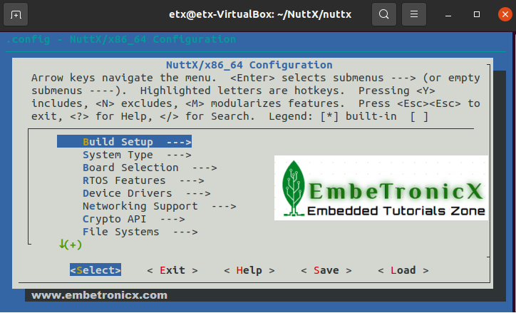
make menuconfig
This will give you a one-green color screen like the below image.
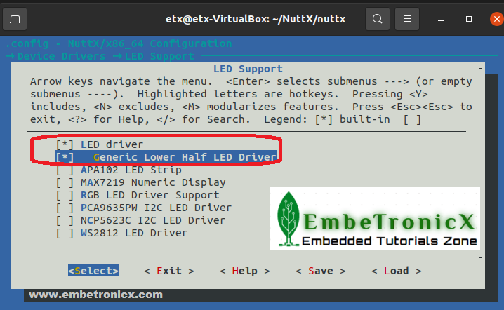
To add the Device driver for the LED, navigate to Device Drivers —> LED Support and press the space bar to select the LED Support. When you do this, you should get another option called Generic Lower Half LED Driver. Enable this Generic Lower Half LED Driver by pressing the space bar or Click ‘Y‘ to include these changes. In this step, you are adding the driver for the LED. Refer to the below image.
|
|
|
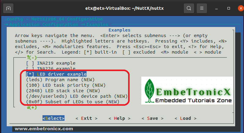
Return to the home menu via ‘Exit’. After enabling the LED Device Driver, then it’s time to add the LED application which controls the LED using the LED device driver which has been added by the previous step. To do that, navigate to Application Configuration —> Examples and select Led Driver Example. Please refer to the below image. You can also configure the application name, task’s priority, stack size, LED device driver path, and Subset of LEDs to use.
We are almost done. Let’s save and exit the menuconfig. Let’s compile the NuttX RTOS by sending the make command.
make[1]: Leaving directory '/home/etx/NuttX/nuttx/arch/xtensa/src'
CP: nuttx.hex
CP: nuttx.bin
MKIMAGE: ESP32 binary
esptool.py -c esp32 elf2image -fs 4MB -fm dio -ff 40m -o nuttx.bin nuttx
esptool.py v3.1-dev
Merged 1 ELF section
Generated: nuttx.bin (ESP32 compatible)
Our nuttx.bin is ready.
|
|
|
Flash
It is time to flash. Connect your ESP32 board to your Linux hosting machine and run the below esptool command.
sudo esptool.py --chip esp32 --port /dev/ttyUSB0 --baud 921600 write_flash 0x1000 bootloader.bin 0x8000 partitions.bin 0x10000 nuttx.bin
We have got the bootloader.bin and partitions.bin from the previous tutorial.
Note:
If you want to combine both make and flash, you can simply run the below command.
make download ESPTOOL_PORT=/dev/ttyUSB0
|
|
|
After it is connecting, you have to press and hold the BOOT button of the ESP32 board (IO0 pin). Then it will flash the code to ESP32. You will get the below prints.
Connecting........_____....._
Chip is ESP32-D0WDQ6 (revision 1)
Features: WiFi, BT, Dual Core, 240MHz, VRef calibration in efuse, Coding Scheme None
Crystal is 40MHz
MAC: 7c:9e:bd:06:e9:48
Uploading stub...
Running stub...
Stub running...
Changing baud rate to 921600
Changed.
Configuring flash size...
Auto-detected Flash size: 4MB
Flash will be erased from 0x00010000 to 0x0002efff...
Compressed 125024 bytes to 52599...
Wrote 125024 bytes (52599 compressed) at 0x00010000 in 1.4 seconds (effective 690.6 kbit/s)...
Hash of data verified.

Leaving...
Hard resetting via RTS pin..
Blink LED on ESP32 using NuttX RTOS – Output
That’s all. We have flashed the binaries. Let’s Blink LED on ESP32 using NuttX RTOS. To do that, connect the ESP32 using picocom.
Run the below command and press the RESET button (EN Button).
picocom -b 115200 /dev/ttyUSB0
After pressing the RESET button, you will get a NutShell like below.
rst:0x1 (POWERON_RESET),boot:0x13 (SPI_FAST_FLASH_BOOT)
configsip: 0, SPIWP:0xee
clk_drv:0x00,q_drv:0x00,d_drv:0x00,cs0_drv:0x00,hd_drv:0x00,wp_drv:0x00
mode:DIO, clock div:2
load:0x3fff0030,len:6724
load:0x40078000,len:13140
load:0x40080400,len:3644
entry 0x40080674
I (27) boot: ESP-IDF v4.4-dev-1183-g9d34a1cd4 2nd stage bootloader
I (27) boot: compile time 00:57:50
I (27) boot: chip revision: 1
I (31) boot_comm: chip revision: 1, min. bootloader chip revision: 0
I (38) boot.esp32: SPI Speed      : 40MHz
I (43) boot.esp32: SPI Mode       : DIO
I (47) boot.esp32: SPI Flash Size : 2MB
I (52) boot: Enabling RNG early entropy source...
I (57) boot: Partition Table:
I (61) boot: ## Label            Usage          Type ST Offset   Length
I (68) boot:  0 nvs              WiFi data        01 02 00009000 00006000
I (76) boot:  1 phy_init         RF data          01 01 0000f000 00001000
I (83) boot:  2 factory          factory app      00 00 00010000 00100000
I (91) boot: End of partition table
I (95) boot_comm: chip revision: 1, min. application chip revision: 0
I (102) esp_image: segment 0: paddr=00010020 vaddr=3f400020 size=01c70h (  7280) map
I (113) esp_image: segment 1: paddr=00011c98 vaddr=3ffb1370 size=0005ch (    92) load
I (119) esp_image: segment 2: paddr=00011cfc vaddr=40080000 size=016b8h (  5816) load
I (130) esp_image: segment 3: paddr=000133bc vaddr=00000000 size=0cc5ch ( 52316)
I (155) esp_image: segment 4: paddr=00020020 vaddr=400d0020 size=0e810h ( 59408) map
I (179) boot: Loaded app from partition at offset 0x10000
I (179) boot: Disabling RNG early entropy source...
�
NuttShell (NSH) NuttX-10.1.0-RC1
nsh>
Then enter ‘?‘ or help in the NSH (NutShell). You will get the output like below.
|
|
|
nsh> ?
help usage:  help [-v] [<cmd>]

  .         cat       dd        false     ls        ps        sleep     uname
  [         cd        df        free      mkdir     pwd       source    umount
  ?         cp        echo      help      mkrd      rm        test      unset
  basename  cmp       exec      hexdump   mount     rmdir     time      usleep
  break     dirname   exit      kill      mv        set       true      xd

Builtin Apps:
  sh    nsh   leds
If you see the Builtin Apps:, it has leds application. Let’s Blink LED by running the leds.
nsh> leds

leds_main: Starting the led_daemon
leds_main: led_daemon started
led_daemon: Running
led_daemon: Opening /dev/userleds
led_daemon: Supported LEDs 0x01
led_daemon: LED set 0x01
nsh> led_daemon: LED set 0x00
led_daemon: LED set 0x01
led_daemon: LED set 0x00
led_daemon: LED set 0x01
led_daemon: LED set 0x00
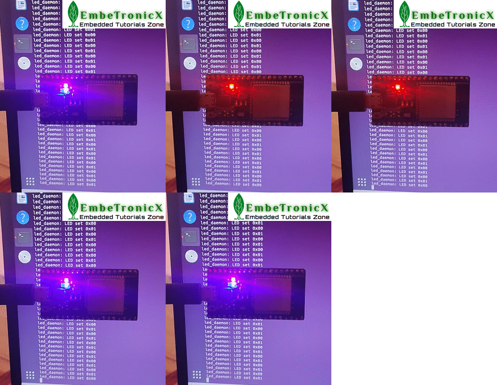
Good work. Now our onboard LED is blinking. Check out the output below.
Reset the ESP32 by pressing the DevKit EN button (RESET) to return to stop the leds application. If you do not have an onboard led, connect an LED to pin 2 and associate a resistor in series (between 100 Ω to 1 k Ω).
printf
We have been writing tutorials for Linux device drivers. In that Linux device driver, we can control the LEDs using the echo command.
|
|
|
For example, If we want to turn on the LED, we do echo 1 > /dev/your_device_driver.
If we want to turn off the LED, we do echo 0 > /dev/your_device_driver.
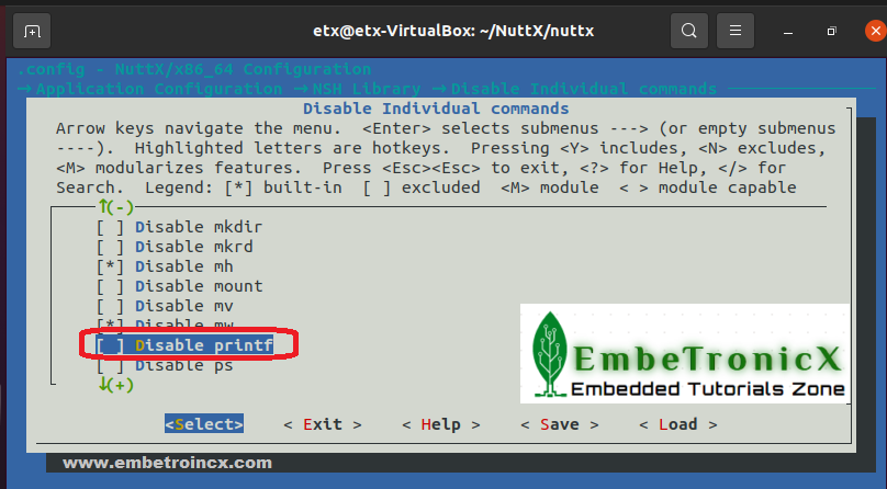
Is there any way like the above examples available in the NuttX RTOS? Yes, there is. But not using the echo command. We can use printf to achieve that. To use the printf, you have to enable that in the menuconfig.
To enable that, do make menuconfig. Then navigate to Application Configuration —> NSH Library —> Disable Individual commands —> uncheck the Disable printf. Refer to the below image.
|
|
|
Then save the configuration and exit. Then do make download ESPTOOL_PORT=/dev/ttyUSB0. This will flash the updated nuttx.bin. You can repeat the steps mentioned here.
Then try the below commands in picocom.
To turn on the LED try to enter the below command in nsh.
printf \x00000001 > /dev/userleds
To turn off the LED try to enter the below command in nsh.
printf \x00000000 > /dev/userleds
In our next tutorial, we will see how to access the other GPIOs on ESP32 using NuttX RTOS.
|
|
|
You can also read the below tutorials.

Embedded Software | Firmware | Linux Devic Deriver | RTOS
Hi, I am a tech blogger and an Embedded Engineer. I am always eager to learn and explore tech-related concepts. And also, I wanted to share my knowledge with everyone in a more straightforward way with easy practical examples. I strongly believe that learning by doing is more powerful than just learning by reading. I love to do experiments. If you want to help or support me on my journey, consider sharing my articles, or Buy me a Coffee! Thank you for reading my blog! Happy learning!

