
This article is a continuation of the Series on Linux Device Drivers and carries the discussion on Linux device drivers and their implementation. The aim of this series is to provide easy and practical examples that anyone can understand. This is the BMP280 I2C Linux Device Driver (Bosch Pressure sensor) – Linux Device Driver Tutorial Part 48.
You can find a video explanation of this tutorial here. You can also find all the Linux device driver’s video playlists here.
Table of Contents
BMP280 I2C Linux Device Driver (Bosch Pressure sensor)
Prerequisites
- I2C Introduction – Part 1 (Basics)
- I2C Introduction – Part 2 (Advanced Topics)
- I2C Client Driver in Linux kernel
- I2C Dummy Driver in Linux kernel
- I2C Bus driver using Bit banging
Hardware Required
- Raspberry Pi 3B
- BMP280 Bosch Pressure sensor
BMP280 Bosch Pressure sensor
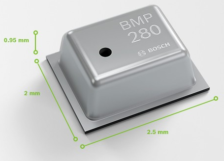
The BMP280 is an absolute barometric pressure sensor, which is especially feasible for mobile applications. Its small dimensions and its low power consumption allow for the implementation in battery-powered devices such as mobile phones, GPS modules, or watches. The BMP280 is based on Bosch’s proven piezo-resistive pressure sensor technology featuring high accuracy and linearity as well as long-term stability and high EMC robustness. Numerous device operation options guarantee for highest flexibility. The device is optimized in terms of power consumption, resolution, and filter performance.
|
|
|
BMP280 Interfacing
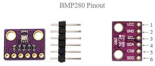
The BMP280 supports the I²C and SPI digital interfaces. It acts as a slave for both protocols. The I²C interface supports the Standard, Fast and High-Speed modes. The SPI interface supports both SPI mode ‘00’ (CPOL = CPHA = ‘0’) and mode ‘11’ (CPOL = CPHA = ‘1’) in 4- wire and 3-wire configurations.
We will be using I2C interfacing in this tutorial. Therefore we have to select an I2C interface, so to do that we need to connect the CSB pin of the sensor module to VDDIO.
There are two slave addresses of I2C in BMP280, if we connect SDO to GND then the slave address is 110110 (0x76), Connecting SDO to VDDIO results in a slave address of 1110111 (0x77). We will connect SDO to GND in this tutorial.
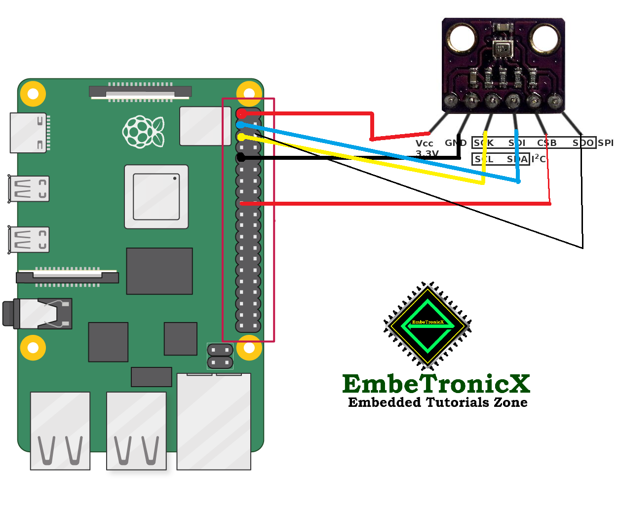
Connection Diagram
- Vcc – PIN1
- GND – PIN 9
- SCL – PIN 5
- SDA – PIN 3
- CSB – PIN 17
- SDO – PIN 6
BMP280 Linux Device Driver Code
BMP280 driver code is provided by Bosch in their GitHub repository. We will download that code and will integrate it with our Linux I2C Driver code.
|
|
|
The link for the GitHub repository is github.com/BoschSensortec/BMP280_driver. We need four files (bmp280.c, bmp280.h, bmp280_defs.h and examples/pressure.c). After downloading these files, we will integrate them with Linux I2C client driver code as given in this tutorial.
Integrating BMP280 Code with I2C Driver Code
There are four driver functions from Linux I2C Driver as shown below.
static int etx_open(struct inode *inode, struct file *file)
{
}

static int etx_release(struct inode *inode, struct file *file)
{
}

ssize_t etx_read(struct file *filp,
            	char __user *buf, size_t len, loff_t *off)
{
}

static ssize_t etx_write(struct file *filp,
            	const char __user *buf, size_t len, loff_t *off)
{
}
These functions will be called when we read/write from the bmp280 Linux driver file.
And there are two more functions that will be called when we load and unload the bmp280 Linux driver file.
static int __init etx_driver_init(void)
{
}

static void __exit etx_driver_exit(void)
{
}
We will follow the same steps as given in this tutorial.
|
|
|
So first we will allocate a Major number to our driver and then we will add a driver to the system and then we will create the device as shown in the following code.
static int __init etx_driver_init(void)
{


  /*Allocating Major number*/
  if((alloc_chrdev_region(&dev, 0, 1, "etx_Dev")) <0){
  pr_err("Cannot allocate major number\n");
  return -1;
  }
  pr_info("Major = %d Minor = %d \n",MAJOR(dev), MINOR(dev));

  /*Creating cdev structure*/
  cdev_init(&etx_cdev,&fops);

  /*Adding character device to the system*/
  if((cdev_add(&etx_cdev,dev,1)) < 0){
  pr_err("Cannot add the device to the system\n");
  return -1;
  }

  /*Creating struct class*/
  if(IS_ERR(dev_class = class_create(THIS_MODULE,"etx_class"))){
  pr_err("Cannot create the struct class\n");
  return -1;
  }

  /*Creating device*/
  if(IS_ERR(device_create(dev_class,NULL,dev,NULL,"etx_device"))){
  pr_err( "Cannot create the Device \n");
  return -1;
  }
  int ret = -1;
  etx_i2c_adapter 	= i2c_get_adapter(I2C_BUS_AVAILABLE);

  if( etx_i2c_adapter != NULL )
  {
  	  pr_info("i2c_adapter added\n");
    	etx_i2c_client_bmp = i2c_new_client_device(etx_i2c_adapter, &bmp_i2c_board_info);

    	if( etx_i2c_client_bmp != NULL )
    	{
        	pr_info("i2c_client added\n");
        	i2c_add_driver(&etx_bmp_driver);
        	ret = 0;
    	}

    	i2c_put_adapter(etx_i2c_adapter);
  }

  pr_info("Driver Added!!!\n");
  return ret;
}
After etx_driver_init function etx_bmp_probe will be called. In the probe function, we will init the bmp280 sensor as shown below.
/*
** This function getting called when the slave has been found
** Note : This will be called only once when we load the driver.
*/
static int etx_bmp_probe(struct i2c_client *client,
                     	const struct i2c_device_id *id)
{
  int8_t rslt;

  uint32_t pres32, pres64;
  double pres;


  /* Assign device I2C address based on the status of SDO pin (GND for PRIMARY(0x76) & VDD for SECONDARY(0x77)) */
  bmp.dev_id = BMP280_I2C_ADDR_PRIM;

  /* Select the interface mode as I2C */
  bmp.intf = BMP280_I2C_INTF;

  /* Map the I2C read & write function pointer with the functions responsible for I2C bus transfer */
  bmp.read = i2c_reg_read;
  bmp.write = i2c_reg_write;

 	rslt = bmp280_init(&bmp);

  /* Always read the current settings before writing, especially when
 	* all the configuration is not modified
 	*/
  rslt = bmp280_get_config(&conf, &bmp);

  /* configuring the temperature oversampling, filter coefficient and output data rate */
  /* Overwrite the desired settings */
  conf.filter = BMP280_FILTER_COEFF_2;

  /* Pressure oversampling set at 4x */
  conf.os_pres = BMP280_OS_4X;

  /* Setting the output data rate as 1HZ(1000ms) */
  conf.odr = BMP280_ODR_1000_MS;
  rslt = bmp280_set_config(&conf, &bmp);

  /* Always set the power mode after setting the configuration */
  rslt = bmp280_set_power_mode(BMP280_NORMAL_MODE, &bmp);

  /* Reading the raw data from sensor */
  rslt = bmp280_get_uncomp_data(&ucomp_data, &bmp);

  /* Getting the compensated pressure using 32 bit precision */
  rslt = bmp280_get_comp_pres_32bit(&pres32, ucomp_data.uncomp_press, &bmp);

  pr_info("UP: %ld, P32: %ld \r\n",
           	ucomp_data.uncomp_press,
           	pres32);

  pr_info("bmp Probed!!!\n");

  return 0;
}
As shown above, we have assigned bmp.read to i2c_reg_read and bmp.write to i2c_reg_write.
  /* Map the I2C read & write function pointer with the functions responsible for I2C bus transfer */
  bmp.read = i2c_reg_read;
  bmp.write = i2c_reg_write;
So, we will call Linux I2C read and write functions in i2c_reg_read and i2c_reg_write respectively.
/*!
* @brief Function for writing the sensor's registers through I2C bus.
*
* @param[in] i2c_addr : sensor I2C address.
* @param[in] reg_addr : Register address.
* @param[in] reg_data : Pointer to the data buffer whose value is to be written.
* @param[in] length : No of bytes to write.
*
* @return Status of execution
* @retval 0 -> Success
* @retval >0 -> Failure Info
*
*/
int8_t i2c_reg_write(uint8_t i2c_addr, uint8_t reg_addr, uint8_t *reg_data, uint16_t length)
{
/* Implement the I2C write routine according to the target machine. */
uint8_t tx_data[100] = {0};
tx_data[0] = reg_addr;
uint16_t i=0;
for(i=0; i<length; i++) tx_data[i + 1] = reg_data[i];
int ret = i2c_master_send(etx_i2c_client_bmp, tx_data, length + 1);
return ret;
}
/*!
* @brief Function for reading the sensor's registers through I2C bus.
*
* @param[in] i2c_addr : Sensor I2C address.
* @param[in] reg_addr : Register address.
* @param[out] reg_data : Pointer to the data buffer to store the read data.
* @param[in] length : No of bytes to read.
*
* @return Status of execution
* @retval 0 -> Success
* @retval >0 -> Failure Info
*
*/
int8_t i2c_reg_read(uint8_t i2c_addr, uint8_t reg_addr, uint8_t *reg_data, uint16_t length)
{
/* Implement the I2C read routine according to the target machine. */
int ret = i2c_master_send(etx_i2c_client_bmp, ®_addr, 1);
ret |= i2c_master_recv(etx_i2c_client_bmp, reg_data, length);
return ret;
}
When we read the data from the BMP280 Linux driver file using the cat command, the following function will be called.
|
|
|
/*
** This function will be called when we read the Device file
*/
static ssize_t etx_read(struct file *filp,
            	char __user *buf, size_t len, loff_t *off)
{
   uint32_t pres32;
  bmp280_get_uncomp_data(&ucomp_data, &bmp);

  /* Getting the compensated pressure using 32 bit precision */
 	bmp280_get_comp_pres_32bit(&pres32, ucomp_data.uncomp_press, &bmp);

  //write to user
  len = 4;
  if( copy_to_user(buf, (char*)&pres32, len) > 0) {
  pr_err("ERROR: Not all the bytes have been copied to user\n");
  }

  pr_info("Preassure value = %d \n", pres32);

  return 0;
}
In the above code, we are reading the pressure value from the sensor and printing it into the kernel log.
When we unload the driver from the kernel the following function will be called.
/*
** This function getting called when the slave has been removed
** Note : This will be called only once when we unload the driver.
*/
static int etx_bmp_remove(struct i2c_client *client)
{
  // put sensor in sleep mode
  bmp280_set_power_mode(BMP280_SLEEP_MODE, &bmp);

  pr_info("bmp Removed!!!\n");
  return 0;
}
The above code puts the BMP280 Sensor in sleep mode. After execution of etx_bmp_remove then etx_driver_exit will be called.
/*
** Module Exit function
*/
static void __exit etx_driver_exit(void)
{
  i2c_unregister_device(etx_i2c_client_bmp);
  i2c_del_driver(&etx_bmp_driver);
  device_destroy(dev_class,dev);
  class_destroy(dev_class);
  cdev_del(&etx_cdev);
  unregister_chrdev_region(dev, 1);
  pr_info("Driver Removed!!!\n");
}
The above function unregisters and deletes the BMP280 I2C driver from Linux Kernel and destroys the device class.
The whole source code for the driver file can be found on GitHub in the driver.c file.
|
|
|
Makefile
The Makefile for the driver code is shown below.
obj-m += driver.o

KDIR = /lib/modules/$(shell uname -r)/build


all:
  make -C $(KDIR)  M=$(shell pwd) modules

clean:
  make -C $(KDIR)  M=$(shell pwd) clean
Testing the Device Driver
- Compile the driver using
make all - Then load the driver using
sudo insmod driver.ko - Once the driver is loaded, we can read the driver file using
sudo cat /dev/etx_device - Now, check the
dmesg - You should see the pressure value in the kernel log.
- Unload the driver using
sudo rmmod driver
Output Video
You can check the below demo video.
Please find the other Linux device driver tutorials here.
Reference
You can also read the below tutorials.
|
|
|

Passionate Embedded Software developer, Loves to solve problem, Enthusiastic in electronics, programming and DSP. Graduated in Electronics and Communication Engineering.
