his article is a continuation of the Series on Linux Device Drivers and carries the discussion on Linux device drivers and their implementation. The aim of this series is to provide easy and practical examples that anyone can understand. This is the I2C Bus Linux Device Driver using I2C-GPIO using Raspberry PI – Linux Device Driver Tutorial Part 40.
You can also read BMP280 Bosch Pressure Sensor I2C Device Driver, I2C dummy bus driver, I2C client driver, Sysfs, Procfs, Workqueue, Completion, Softirq, and threaded IRQ in the Linux device driver.
We are using the Raspberry PI 4 Model B for this demonstration.
Table of Contents
I2C Bus Linux Device Driver using I2C-GPIO
Prerequisites
- I2C Introduction – Part 1 (Basics)
- I2C Introduction – Part 2 (Advanced Topics)
- I2C Client Driver in Linux kernel
- I2C Dummy Driver in Linux kernel
- GPIO Linux Driver
- I2C Bus driver using Bit banging
Hardware Required
- Raspberry Pi
- SSD1306 OLED I2C Display
Bring up Raspberry PI
- Install Raspberry Pi OS (32-bit) with desktop in the SD card.
- Then install the kernel header using
sudo apt install raspberrypi-kernel-headers
For your information, In our Raspberry PI 4 board, kernel 5.4.51-v7l+ is installed.
Please enable the I2C in the Raspberry Pi.
|
|
|
Introduction
In our last tutorial, we have implemented everything using Bit banging right from the START condition, STOP condition, Read ACK/NACK, etc. But we have not taken care of advanced I2C operations like arbitration, clock stretching, etc. So even if we implement that we have to test it fully. Maybe our approach will take more time than normal.
So in this tutorial, we are going to use i2c-gpio driver where all the START condition, STOP condition, ACK/NACK, Arbitration, clock stretching, etc are implemented (bit-banging) and it has been tested fully as it is part of the Linux kernel. So we will see how to use that. Let’s get started.
APIs used for the I2C bus driver
struct i2c_algo_bit_data
/*
 * This struct contains the hw-dependent functions of bit-style adapters to
 * manipulate the line states, and to init any hw-specific features. This is
 * only used if you have more than one hw-type of adapter running.
 */
struct i2c_algo_bit_data {
    void *data;     /* private data for lowlevel routines */
    void (*setsda) (void *data, int state);
    void (*setscl) (void *data, int state);
    int  (*getsda) (void *data);
    int  (*getscl) (void *data);
    int  (*pre_xfer)  (struct i2c_adapter *);
    void (*post_xfer) (struct i2c_adapter *);

    /* local settings */
    int udelay;     /* half clock cycle time in us,
                   minimum 2 us for fast-mode I2C,
                   minimum 5 us for standard-mode I2C and SMBus,
                   maximum 50 us for SMBus */
    int timeout;        /* in jiffies */
    bool can_do_atomic; /* callbacks don't sleep, we can be atomic */
};
If you see the structure, setscl, getscl, setsda, getsda are present. We have to give our callback function to these members. For example, If the i2c-gpio driver wants to send the START condition, it needs to set the SCL/SDA GPIO to High/Low. But it doesn’t know which GPIO we are using. That’s why they have made this as a callback. See the example code given below to understand more.
data – private data (Optional)
pre_xfer – Function that will be called before i2C-gpio starts the I2C transfer (Optional)
|
|
|
post_xfer – Function that will be called after i2C-gpio finishes the I2C transfer (Optional)
delay – delay in uS
timout – Timeout in jiffies
can_do_atomic – This will tells callback can sleep or not (Optional)
i2c_adapter structure’s algo_data member. Make sure that you have requested the GPIO before accessing it.Example
#define ADAPTER_NAME     "ETX_I2C_ADAPTER"

#define SCL_GPIO  20    //GPIO act as SCL
#define SDA_GPIO  21    //GPIO act as SDA

/*
** Function to read the SCL GPIO
*/
static int ETX_I2C_Read_SCL(void *data)
{
  gpio_direction_input(SCL_GPIO);
  return gpio_get_value(SCL_GPIO);
}

/*
** Function to read the SDA GPIO
*/
static int ETX_I2C_Read_SDA(void *data)
{
  gpio_direction_input(SDA_GPIO);
  return gpio_get_value(SDA_GPIO);
}

/*
** Function to set the SCL GPIO
*/
static void ETX_I2C_Set_SCL(void *data, int state)
{
  gpio_direction_output(SCL_GPIO, state);
  gpio_set_value(SCL_GPIO, state);
}

/*
** Function to set the SDA GPIO
*/
static void ETX_I2C_Set_SDA(void *data, int state)
{
  gpio_direction_output(SDA_GPIO, state);
  gpio_set_value(SDA_GPIO, state);
}

/*
** I2C bit algorithm Structure
*/
struct i2c_algo_bit_data etx_bit_data = {
  .setsda = ETX_I2C_Set_SDA,
  .setscl = ETX_I2C_Set_SCL,
  .getscl = ETX_I2C_Read_SCL,
  .getsda = ETX_I2C_Read_SDA,
  .udelay = 5,
  .timeout = 100,       /* 100 ms */
};

/*
** I2C adapter Structure
*/
static struct i2c_adapter etx_i2c_adapter = {
  .owner      = THIS_MODULE,
  .class      = I2C_CLASS_HWMON | I2C_CLASS_SPD,
  .name       = ADAPTER_NAME,
  .algo_data  = &etx_bit_data,
  .nr         = 5,
};
i2c_bit_add_bus
This API is used to register the adapter to the subsystem. But this will assign the dynamic bus number.
|
|
|
|
where, It returns zero when a new bus number was allocated and stored in |
i2c_bit_add_numbered_bus
This API is used to register the adapter to the subsystem. But it assigns the number that we asked for if only it is available. We have to initialize the member called nr in the i2c_adapter structure before calling this.
|
Where, This returns zero when the specified adapter is available for clients using the bus number provided in |
I think we have discussed other APIs in our previous tutorials. So we can jump into the programming now.
Example Programming
In this tutorial, we will demonstrate the same example (last tutorial’s) which fills data in the display while loading the module and clears the display while unloading the module. The only difference from the last tutorial is the code that we are using in the bus driver.
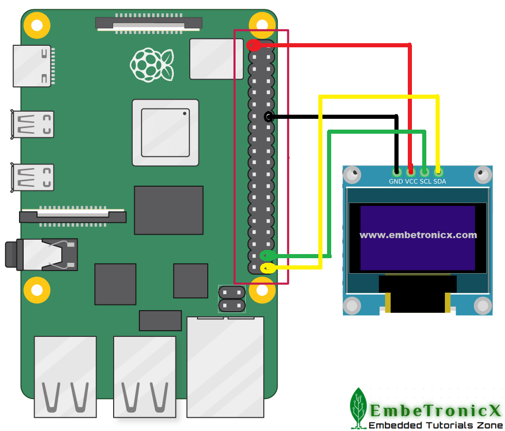
Connection Diagram
- SCL – GPIO 20
- SDA – GPIO 21
|
|
|
I2C Bus Driver Source Code
[Get the source code from GitHub]
/***************************************************************************//**
*  \file       driver_bus.c
*
*  \details    Simple I2C Bus driver explanation
*
*  \author     EmbeTronicX
*
*  \Tested with Linux raspberrypi 5.4.51-v7l+
*
* *******************************************************************************/
#include <linux/module.h>
#include <linux/init.h>
#include <linux/slab.h>
#include <linux/i2c.h>
#include <linux/delay.h>
#include <linux/kernel.h>
#include <linux/gpio.h>
#include <linux/i2c-algo-bit.h>

#define ADAPTER_NAME     "ETX_I2C_ADAPTER"

#define SCL_GPIO  20    //GPIO act as SCL
#define SDA_GPIO  21    //GPIO act as SDA

/*
** Function to read the SCL GPIO
*/
static int ETX_I2C_Read_SCL(void *data)
{
  gpio_direction_input(SCL_GPIO);
  return gpio_get_value(SCL_GPIO);
}

/*
** Function to read the SDA GPIO
*/
static int ETX_I2C_Read_SDA(void *data)
{
  gpio_direction_input(SDA_GPIO);
  return gpio_get_value(SDA_GPIO);
}

/*
** Function to set the SCL GPIO
*/
static void ETX_I2C_Set_SCL(void *data, int state)
{
  gpio_direction_output(SCL_GPIO, state);
  gpio_set_value(SCL_GPIO, state);
}

/*
** Function to set the SDA GPIO
*/
static void ETX_I2C_Set_SDA(void *data, int state)
{
  gpio_direction_output(SDA_GPIO, state);
  gpio_set_value(SDA_GPIO, state);
}

/*
** Function to Initialize the GPIOs
*/
static int ETX_I2C_Init( void )
{
  int ret = 0;

  pr_info("In %s\n", __func__);
  do      //Break if any error
  {
    //Checking the SCL GPIO is valid or not
    if(gpio_is_valid(SCL_GPIO) == false){
          pr_err("SCL GPIO %d is not valid\n", SCL_GPIO);
          ret = -1;
          break;
    }

    //Checking the SDA GPIO is valid or not
    if(gpio_is_valid(SDA_GPIO) == false){
          pr_err("SDA GPIO %d is not valid\n", SDA_GPIO);
          ret = -1;
          break;
    }

    //Requesting the SCL GPIO
    if(gpio_request(SCL_GPIO,"SCL_GPIO") < 0){
          pr_err("ERROR: SCL GPIO %d request\n", SCL_GPIO);
          ret = -1;
          break;
    }

    //Requesting the SDA GPIO
    if(gpio_request(SDA_GPIO,"SDA_GPIO") < 0){
          pr_err("ERROR: SDA GPIO %d request\n", SDA_GPIO);
          //free already requested SCL GPIO
          gpio_free(SCL_GPIO);
          ret = -1;
          break;
    }

    /*
    ** configure the SCL GPIO as output, We will change the
    ** direction later as per our need.
    */
    gpio_direction_output(SCL_GPIO, 1);

    /*
    ** configure the SDA GPIO as output, We will change the
    ** direction later as per our need.
    */
    gpio_direction_output(SDA_GPIO, 1);

  } while(false);

  return ret;
}

/*
** Function to Deinitialize the GPIOs
*/
static void ETX_I2C_DeInit( void )
{
  //free both the GPIOs
  gpio_free(SCL_GPIO);
  gpio_free(SDA_GPIO);
}

/*
** I2C bit algorithm Structure
*/
struct i2c_algo_bit_data etx_bit_data = {
  .setsda = ETX_I2C_Set_SDA,
  .setscl = ETX_I2C_Set_SCL,
  .getscl = ETX_I2C_Read_SCL,
  .getsda = ETX_I2C_Read_SDA,
  .udelay = 5,
  .timeout = 100,       /* 100 ms */
};

/*
** I2C adapter Structure
*/
static struct i2c_adapter etx_i2c_adapter = {
  .owner      = THIS_MODULE,
  .class      = I2C_CLASS_HWMON | I2C_CLASS_SPD,
  .name       = ADAPTER_NAME,
  .algo_data  = &etx_bit_data,
  .nr         = 5,
};


/*
** Module Init function
*/
static int __init etx_driver_init(void)
{
  int ret = -1;

  ETX_I2C_Init();

  ret = i2c_bit_add_numbered_bus(&etx_i2c_adapter);

  pr_info("Bus Driver Added!!!\n");

  return ret;
}

/*
** Module Exit function
*/
static void __exit etx_driver_exit(void)
{
  ETX_I2C_DeInit();
  i2c_del_adapter(&etx_i2c_adapter);
  pr_info("Bus Driver Removed!!!\n");
}

module_init(etx_driver_init);
module_exit(etx_driver_exit);

MODULE_LICENSE("GPL");
MODULE_AUTHOR("EmbeTronicX <[email protected]>");
MODULE_DESCRIPTION("Simple I2C Bus driver explanation");
MODULE_VERSION("1.39");
Makefile
obj-m += driver_bus.o

KDIR = /lib/modules/$(shell uname -r)/build


all:
    make -C $(KDIR)  M=$(shell pwd) modules

clean:
    make -C $(KDIR)  M=$(shell pwd) clean
2C Client Device Driver Source code
There are no modifications in the client driver from the last tutorial.
[Get the source code from GitHub]
/***************************************************************************//**
*  \file       driver_client.c
*
*  \details    Simple I2C driver explanation (SSD_1306 OLED Display Interface)
*
*  \author     EmbeTronicX
*
*  \Tested with Linux raspberrypi 5.4.51-v7l+
*
* *******************************************************************************/
#include <linux/module.h>
#include <linux/init.h>
#include <linux/slab.h>
#include <linux/i2c.h>
#include <linux/delay.h>
#include <linux/kernel.h>

#define I2C_BUS_AVAILABLE   (          5 )              // I2C Bus available in our Raspberry Pi
#define SLAVE_DEVICE_NAME   ( "ETX_OLED" )              // Device and Driver Name
#define SSD1306_SLAVE_ADDR  (       0x3C )              // SSD1306 OLED Slave Address

static struct i2c_adapter *etx_i2c_adapter     = NULL;  // I2C Adapter Structure
static struct i2c_client  *etx_i2c_client_oled = NULL;  // I2C Cient Structure (In our case it is OLED)

/*
** This function writes the data into the I2C client
**
**  Arguments:
**      buff -> buffer to be sent
**      len  -> Length of the data
**
*/
static int I2C_Write(unsigned char *buf, unsigned int len)
{
  /*
  ** Sending Start condition, Slave address with R/W bit,
  ** ACK/NACK and Stop condtions will be handled internally.
  */
  int ret = i2c_master_send(etx_i2c_client_oled, buf, len);

  return ret;
}

/*
** This function reads one byte of the data from the I2C client
**
**  Arguments:
**      out_buff -> buffer wherer the data to be copied
**      len      -> Length of the data to be read
**
*/
static int I2C_Read(unsigned char *out_buf, unsigned int len)
{
  /*
  ** Sending Start condition, Slave address with R/W bit,
  ** ACK/NACK and Stop condtions will be handled internally.
  */
  int ret = i2c_master_recv(etx_i2c_client_oled, out_buf, len);

  return ret;
}

/*
** This function is specific to the SSD_1306 OLED.
** This function sends the command/data to the OLED.
**
**  Arguments:
**      is_cmd -> true = command, flase = data
**      data   -> data to be written
**
*/
static void SSD1306_Write(bool is_cmd, unsigned char data)
{
  unsigned char buf[2] = {0};
  int ret;

  /*
  ** First byte is always control byte. Data is followed after that.
  **
  ** There are two types of data in SSD_1306 OLED.
  ** 1. Command
  ** 2. Data
  **
  ** Control byte decides that the next byte is, command or data.
  **
  ** -------------------------------------------------------
  ** |              Control byte's | 6th bit  |   7th bit  |
  ** |-----------------------------|----------|------------|
  ** |   Command                   |   0      |     0      |
  ** |-----------------------------|----------|------------|
  ** |   data                      |   1      |     0      |
  ** |-----------------------------|----------|------------|
  **
  ** Please refer the datasheet for more information.
  **
  */
  if( is_cmd == true )
  {
      buf[0] = 0x00;
  }
  else
  {
      buf[0] = 0x40;
  }

  buf[1] = data;

  ret = I2C_Write(buf, 2);
}


/*
** This function sends the commands that need to used to Initialize the OLED.
**
**  Arguments:
**      none
**
*/
static int SSD1306_DisplayInit(void)
{
  msleep(100);               // delay

  /*
  ** Commands to initialize the SSD_1306 OLED Display
  */
  SSD1306_Write(true, 0xAE); // Entire Display OFF
  SSD1306_Write(true, 0xD5); // Set Display Clock Divide Ratio and Oscillator Frequency
  SSD1306_Write(true, 0x80); // Default Setting for Display Clock Divide Ratio and Oscillator Frequency that is recommended
  SSD1306_Write(true, 0xA8); // Set Multiplex Ratio
  SSD1306_Write(true, 0x3F); // 64 COM lines
  SSD1306_Write(true, 0xD3); // Set display offset
  SSD1306_Write(true, 0x00); // 0 offset
  SSD1306_Write(true, 0x40); // Set first line as the start line of the display
  SSD1306_Write(true, 0x8D); // Charge pump
  SSD1306_Write(true, 0x14); // Enable charge dump during display on
  SSD1306_Write(true, 0x20); // Set memory addressing mode
  SSD1306_Write(true, 0x00); // Horizontal addressing mode
  SSD1306_Write(true, 0xA1); // Set segment remap with column address 127 mapped to segment 0
  SSD1306_Write(true, 0xC8); // Set com output scan direction, scan from com63 to com 0
  SSD1306_Write(true, 0xDA); // Set com pins hardware configuration
  SSD1306_Write(true, 0x12); // Alternative com pin configuration, disable com left/right remap
  SSD1306_Write(true, 0x81); // Set contrast control
  SSD1306_Write(true, 0x80); // Set Contrast to 128
  SSD1306_Write(true, 0xD9); // Set pre-charge period
  SSD1306_Write(true, 0xF1); // Phase 1 period of 15 DCLK, Phase 2 period of 1 DCLK
  SSD1306_Write(true, 0xDB); // Set Vcomh deselect level
  SSD1306_Write(true, 0x20); // Vcomh deselect level ~ 0.77 Vcc
  SSD1306_Write(true, 0xA4); // Entire display ON, resume to RAM content display
  SSD1306_Write(true, 0xA6); // Set Display in Normal Mode, 1 = ON, 0 = OFF
  SSD1306_Write(true, 0x2E); // Deactivate scroll
  SSD1306_Write(true, 0xAF); // Display ON in normal mode

  return 0;
}

/*
** This function Fills the complete OLED with this data byte.
**
**  Arguments:
**      data  -> Data to be filled in the OLED
**
*/
static void SSD1306_Fill(unsigned char data)
{
  unsigned int total  = 128 * 8;  // 8 pages x 128 segments x 8 bits of data
  unsigned int i      = 0;

  //Fill the Display
  for(i = 0; i < total; i++)
  {
      SSD1306_Write(false, data);
  }
}

/*
** This function getting called when the slave has been found
** Note : This will be called only once when we load the driver.
*/
static int etx_oled_probe(struct i2c_client *client,
                         const struct i2c_device_id *id)
{
  SSD1306_DisplayInit();

  //fill the OLED with this data
  SSD1306_Fill(0xFF);

  pr_info("OLED Probed!!!\n");

  return 0;
}

/*
** This function getting called when the slave has been removed
** Note : This will be called only once when we unload the driver.
*/
static int etx_oled_remove(struct i2c_client *client)
{
  //fill the OLED with this data
  SSD1306_Fill(0x00);

  pr_info("OLED Removed!!!\n");
  return 0;
}

/*
** Structure that has slave device id
*/
static const struct i2c_device_id etx_oled_id[] = {
  { SLAVE_DEVICE_NAME, 0 },
  { }
};
MODULE_DEVICE_TABLE(i2c, etx_oled_id);

/*
** I2C driver Structure that has to be added to linux
*/
static struct i2c_driver etx_oled_driver = {
  .driver = {
      .name   = SLAVE_DEVICE_NAME,
      .owner  = THIS_MODULE,
  },
  .probe          = etx_oled_probe,
  .remove         = etx_oled_remove,
  .id_table       = etx_oled_id,
};

/*
** I2C Board Info strucutre
*/
static struct i2c_board_info oled_i2c_board_info = {
  I2C_BOARD_INFO(SLAVE_DEVICE_NAME, SSD1306_SLAVE_ADDR)
};

/*
** Module Init function
*/
static int __init etx_driver_init(void)
{
  int ret = -1;
  etx_i2c_adapter     = i2c_get_adapter(I2C_BUS_AVAILABLE);

  if( etx_i2c_adapter != NULL )
  {
      etx_i2c_client_oled = i2c_new_device(etx_i2c_adapter, &oled_i2c_board_info);

      if( etx_i2c_client_oled != NULL )
      {
          i2c_add_driver(&etx_oled_driver);
          ret = 0;
      }

      i2c_put_adapter(etx_i2c_adapter);
  }

  pr_info("Driver Added!!!\n");
  return ret;
}

/*
** Module Exit function
*/
static void __exit etx_driver_exit(void)
{
  i2c_unregister_device(etx_i2c_client_oled);
  i2c_del_driver(&etx_oled_driver);
  pr_info("Driver Removed!!!\n");
}

module_init(etx_driver_init);
module_exit(etx_driver_exit);

MODULE_LICENSE("GPL");
MODULE_AUTHOR("EmbeTronicX <[email protected]>");
MODULE_DESCRIPTION("Simple I2C driver explanation (SSD_1306 OLED Display Interface)");
MODULE_VERSION("1.38");
Makefile
obj-m += driver_client.o

KDIR = /lib/modules/$(shell uname -r)/build


all:
    make -C $(KDIR)  M=$(shell pwd) modules

clean:
    make -C $(KDIR)  M=$(shell pwd) clean
Testing the Device Driver
- Build the driver by using Makefile (
sudo make) in both bus and client driver directories. - Before loading the bus driver, we should load the i2c-gpio driver. Use
sudo modprobe i2c-gpioto load the i2c-gpio driver. - Load the bus driver using
sudo insmod driver_bus.ko - Load the client driver using
sudo insmod driver_client.ko - See the Display is filled.
- Unload the driver using
sudo rmmod driver_client - See the Display has been cleared.
- Unload the driver using
sudo rmmod driver_bus - Unload the i2c-gpio using
sudo modprobe -r i2c-gpio
Output Video
Click here if you don’t see the output video
In our next tutorial, we will discuss the complete SSD1306 display driver.
|
|
|
Please find the other Linux device driver tutorials here.
You can also read the below tutorials.
Embedded Software | Firmware | Linux Devic Deriver | RTOS
Hi, I am a tech blogger and an Embedded Engineer. I am always eager to learn and explore tech-related concepts. And also, I wanted to share my knowledge with everyone in a more straightforward way with easy practical examples. I strongly believe that learning by doing is more powerful than just learning by reading. I love to do experiments. If you want to help or support me on my journey, consider sharing my articles, or Buy me a Coffee! Thank you for reading my blog! Happy learning!
