This article is a continuation of the Series on STM32 MikroC Bootloader Development and carries the discussion on Bootloader design and implementation. The aim of this series is to provide easy and practical examples that anyone can understand. This post is STM32 MikroC Bootloader using SD Card– Bootloader Tutorial Part 3. In this post, we are going to modify the bootloader code from the previous tutorial, and going to add the SD card feature.
Table of Contents
Prerequisites
In this simple STM32 MikroC bootloader example, we will be using the concepts which have been explained already in the below-given tutorials. So I would request you to go through those tutorials first if you are not familiar with those topics.
- Bootloader Basics – Part 1
- Simple STM32 MikroC Bootloader (Updating application through UART) – Part 2
If you want to develop the bootloader for STM32 with STM32CubeIDE, please refer to these tutorials.
Hardware/Software Required
In this demo, we have used the below components and software.
We have our own EmbeTronicX Store called ChipTronicX. You can purchase the hardware from ChipTronicX.
|
|
|
- STM32F411 Microcontroller (You can use any other stm32 controller. But you need to set the proper flash address)
- SD Card Reader
- USB to UART Converter
- MikroC Pro for ARM IDE
STM32 MikroC Bootloader using SD Card
In our last tutorial, we developed a simple STM32 MikroC Bootloader, and using that, we were updating the application through UART. We have updated the source code on top of the previous tutorial.
Connection
- LED – PC13 (Onboard LED)
- UART 1 (PA9, PA10) – For data transfer (115200Bps) (Use USB to Serial converter)
- UART 2 (PA2, PA3) – For Debug Prints (115200Bps) (Use USB to Serial converter)
- SD Card Reader (SPI) – (PA8 – CS, PB13 – SPI CLK, PB14 – SPI MISO, PB15 – SPI MOSI) – Make sure you are giving 5V to the SD card reader.
Source code – STM32 SD Card Bootloader
Bootloader Source Code
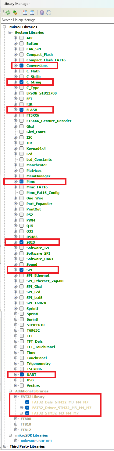
In the project’s Library manager, please enable Conversions, C_String, FLASH, MMC, SDIO, SPI, UART, and FAT32 Libraries. please refer to the below image. Because we are going to use those.
Please check the below-modified bootloader source code. In this source code, we have added two macros called UART_FIRMWARE_UPDATE and SD_CARD_FIRMWARE_UPDATE. You can enable the macro which you want. If you want the Firmware update using UART, then enable UART_FIRMWARE_UPDATE . If you want to enable the Firmware update through an SD card, then enable SD_CARD_FIRMWARE_UPDATE. By default, both will be enabled. You can also find this code on GitHub.
In this example, we are initializing the SPI and FAT32 Library. Then we are checking “Application_STM32.bin” file is present in the SD card. If it is present, then we are updating that firmware in the STM32. Then we are checking the data from the UART1 also for Firmware update. You can disable this feature if you don’t want.
#include "built_in.h"

///////////////////////////////////////////////////////////////////////////////
#pragma orgall 0x40000
#define BOOTLOADER_START_ADDR   0x40000
#define START_PROGRAM_ADDR      0x60000
#define FLASH_DEFAULT_ADDR      0x08000000

#define MAX_BLOCK_SIZE          ( 1024 )                  //1KB
#define MAX_APP_SIZE            ( 262144 )                //256KB
#define FIRMWARE_FILE_NAME      "Application_STM32.bin"

#define UART_FIRMWARE_UPDATE     //Enable this macro for UART Bootloader
#define SD_CARD_FIRMWARE_UPDATE  //Enable this macro for SD Card Bootloader

////////////////////////////////////////////////////////////////////////////////
void Write_Begin();
void FLASH_EraseWrite(unsigned long address);

////////////////////////////////////////////////////////////////////////////////
static char block[MAX_BLOCK_SIZE];

#ifdef SD_CARD_FIRMWARE_UPDATE
#include "__Lib_FAT32.h"
#include "__Lib_MMC.h"

//SPI CS PA8
sbit Mmc_Chip_Select at GPIOA_ODR.B8;

__HANDLE fileHandle;

#endif

//LED Pin PC13
sbit LED at ODR13_GPIOC_ODR_bit;

////////////////////////////////////////////////////////////////////////////////
void Start_Program() org START_PROGRAM_ADDR
{

}
#ifdef SD_CARD_FIRMWARE_UPDATE
////////////////////////////////////////////////////////////////////////////////
void Mmc_TimeoutCallback(char errorCode) {
  // if there was error during the INIT sequence
  if (errorCode == _MMC_INIT_TIMEOUT) {
    UART2_Write_Text("INIT TIMEOUT!!!\r\n");
  }

  // if there was error during the CMD sequence
  if (errorCode == _MMC_CMD_TIMEOUT) {
    UART2_Write_Text("READ TIMEOUT!!!\r\n");
  }

  // if there was error during the SPI sequence
  if (errorCode == _MMC_SPI_TIMEOUT) {
    UART2_Write_Text("SPI TIMEOUT!!!\r\n");
  }
}


////////////////////////////////////////////////////////////////////////////////
void SD_Card_FW_Update( void )
{
  uint32_t size;
  char str[10] = {0};
  uint32_t temp_size = 0;
  uint32_t read_size = 0;
  int del_file = 0;

  UART2_Write_Text("Ok\r\nFiles available in the SD Card:");
  //Set the UART 2 as active. Because FAT32_Dir will send the contents to the
  //Active uart. By default, Active UART will be UART1.
  UART_Set_Active(&UART2_Read, &UART2_Write, &UART2_Data_Ready, &UART2_Tx_Idle);
  FAT32_Dir();
  UART_Write(CR);

  // Open Firmware file with read permission
  UART2_Write_Text("Open Firmware file... ");
  fileHandle = FAT32_Open(FIRMWARE_FILE_NAME, FILE_READ);
  if(fileHandle != 0) {
    UART2_Write_Text("No Firmware File Found!!!\r\n");
  }
  else {
    UART2_Write_Text("OK\r\n");
    FAT32_Size(FIRMWARE_FILE_NAME, &size);
    IntToStr(size, str);
    UART2_Write_Text("Firmware File Size = ");
    UART2_Write_Text(str);
    UART2_Write_Text("\r\n");
    if( size <= MAX_APP_SIZE ) {
      if( size > 0 )  {
        while( temp_size < size ) {
          if( ( size - temp_size ) > MAX_BLOCK_SIZE ) {
            read_size = MAX_BLOCK_SIZE;
          }
          else {
            read_size = ( size - temp_size );
          }

          IntToStr(read_size, str);
          UART2_Write_Text("Read Block Size = ");
          UART2_Write_Text(str);
          UART2_Write_Text("\r\n");

          FAT32_Read(fileHandle, block, read_size);

          if( temp_size == 0 ) {
            //--- If 256 words (1024 bytes) recieved then write to flash
            Write_Begin();
          }
          if(temp_size < BOOTLOADER_START_ADDR) {
            FLASH_EraseWrite(temp_size);
          }

          temp_size += read_size;

          //Clear the memory
          memset( block, 0, MAX_BLOCK_SIZE );
        }
        UART2_Write_Text("SD Card Firmware Update Done!!!\r\n");

        del_file = 1;
      }
    }
    else {
      UART2_Write_Text("App size is maximum, Can't Process...\r\n");
    }
    // Close the file
    FAT32_Close(fileHandle);

    if( del_file == 1 ) {
      UART2_Write_Text("Deleting the Firmware File!!!\r\n");
      //Delete the file
      FAT32_Delete(FIRMWARE_FILE_NAME);
    }
  }
}
#endif

////////////////////////////////////////////////////////////////////////////////
unsigned short UART_Write_Loop(char send, char receive)
{
  unsigned int rslt = 0;

  while(1)
  {
    LED = 1;       // ON PC13
    Delay_ms(20);
    UART_Write(send);
    LED = 0;       // OFF PC13
    Delay_ms(20);

    rslt++;
    if (rslt == 0x64)           // 100 times
    {
      UART2_Write_Text("No data received from UART!!!\r\n");
      return 0;
    }
    if(UART_Data_Ready()) {
      if(UART_Read() == receive)
        return 1;
    }
  }
}
////////////////////////////////////////////////////////////////////////////////
void FLASH_EraseWrite(unsigned long address)
{
  unsigned int i = 0;
  unsigned int dataToWrite;

  FLASH_Unlock();

  for (i = 0; i < 512; i++)
  {
    dataToWrite = block[i * 2] | (block[i * 2 + 1] << 8);
    FLASH_Write_HalfWord( ( address + i*2 + + FLASH_DEFAULT_ADDR ), dataToWrite);
  }

  FLASH_Lock();
}
////////////////////////////////////////////////////////////////////////////////
void Write_Begin()
{
  unsigned int i;
  unsigned long* ptr;
  unsigned char appResetVector[16];
  unsigned long arm_m0_inst;
  unsigned int dataToWrite;

  //LDR R0, PC+X
  arm_m0_inst = 0x4800 + 1;

  appResetVector[0] = arm_m0_inst;
  appResetVector[1] = arm_m0_inst >> 8;

  //MOV SP, R0
  arm_m0_inst = 0x4685;

  appResetVector[2] = arm_m0_inst;
  appResetVector[3] = arm_m0_inst >> 8;

  //LDR R0, PC+Y
  arm_m0_inst = 0x4800 + 1;

  appResetVector[4] = arm_m0_inst;
  appResetVector[5] = arm_m0_inst >> 8;

  //BX R0
  arm_m0_inst = 0x4700;
  appResetVector[6] = arm_m0_inst;
  appResetVector[7] = arm_m0_inst >> 8;

  //SP
  appResetVector[8] = block[0];
  appResetVector[9] = block[1];
  appResetVector[10] = block[2];
  appResetVector[11] = block[3];

  //PC
  appResetVector[12] = block[4];
  appResetVector[13] = block[5];
  appResetVector[14] = block[6];
  appResetVector[15] = block[7];

  FLASH_Unlock();

  //Clear the 7th Sector (App Start Point)
  FLASH_EraseSector(_FLASH_SECTOR_7);

  for (i = 0; i < 8; i++)
  {
    dataToWrite = appResetVector[i * 2] | (appResetVector[i * 2 + 1] << 8);
    FLASH_Write_HalfWord( ( START_PROGRAM_ADDR + FLASH_DEFAULT_ADDR + i*2 ), dataToWrite);
  }

  FLASH_Lock();

  ptr = (unsigned long*)0x00000000;
  block[0] = LoWord(*ptr);
  block[1] = LoWord(*ptr) >> 8;
  block[2] = HiWord(*ptr);
  block[3] = HiWord(*ptr) >> 8;

  ptr++;

  block[4] = LoWord(*ptr);
  block[5] = LoWord(*ptr) >> 8;
  block[6] = HiWord(*ptr);
  block[7] = HiWord(*ptr) >> 8;

  //Erase Application area
  FLASH_EraseSector(_FLASH_SECTOR_0);
  FLASH_EraseSector(_FLASH_SECTOR_1);
  FLASH_EraseSector(_FLASH_SECTOR_2);
  FLASH_EraseSector(_FLASH_SECTOR_3);
  FLASH_EraseSector(_FLASH_SECTOR_4);
  FLASH_EraseSector(_FLASH_SECTOR_5);
}
////////////////////////////////////////////////////////////////////////////////
void Start_Bootload()
{
  unsigned int i = 0;
  char xx, yy;
  long j = 0x0;
  int k =0;
  unsigned int fw_size = 0;
  unsigned int curr_fw_size = 0;

  //Get firmware Size
  //--- Ask for yy
  UART_Write('y');
  while (!UART_Data_Ready()) ;
  //--- Read yy
  yy = UART_Read();
  //--- Ask for xx
  UART_Write('x');
  while (!UART_Data_Ready()) ;
  //--- Read xx
  xx = UART_Read();

  fw_size = yy | (xx << 8);

  while (1) {
    if( (i == MAX_BLOCK_SIZE) || ( curr_fw_size >= fw_size ) ) {
      //--- If 256 words (1024 bytes) recieved then write to flash
      if (!j)
        Write_Begin();
      if (j < BOOTLOADER_START_ADDR) {
        FLASH_EraseWrite(j);
      }

      i = 0;
      j += 0x400;

      for(k=0; k<MAX_BLOCK_SIZE; k++)
      {
        block[k] = 0;
      }
    }
    if( curr_fw_size >= fw_size )
    {
      LED = 1; // OFF PC13
      UART2_Write_Text("UART Firmware Update Done!!!\r\n");
      UART2_Write_Text("Jumping to Application!!!\r\n");
      Delay_ms(2000);
      Start_Program();
    }

    //--- Ask for yy
    UART_Write('y');
    while (!UART_Data_Ready()) ;
    //--- Read yy
    yy = UART_Read();
    //--- Ask for xx
    UART_Write('x');
    while (!UART_Data_Ready()) ;
    //--- Read xx
    xx = UART_Read();
    //--- Save xxyy in block[i]
    block[i++] = yy;
    block[i++] = xx;

    curr_fw_size += 2;
  }
}

void main()
{
  int i;
#ifdef SD_CARD_FIRMWARE_UPDATE
  Mmc_Timeout_Values timeout;
#endif

  GPIO_Digital_Output(&GPIOC_BASE,_GPIO_PINMASK_13);
  UART2_Init(115200);                                        //Debug Print UART

#ifdef SD_CARD_FIRMWARE_UPDATE
  GPIO_Digital_Output(&GPIOA_BASE,_GPIO_PINMASK_8);          //Chip Select
  GPIO_Digital_Output(&GPIOB_BASE, _GPIO_PINMASK_13);        //SPI CLK
  GPIO_Digital_Input(&GPIOB_BASE, _GPIO_PINMASK_14);         //SPI MISO
  GPIO_Digital_Output(&GPIOB_BASE, _GPIO_PINMASK_15);        //SPI MOSI

  UART2_Write_Text("!------Firmware Update using SD Card------!\r\n");
  UART2_Write_Text("Initialize SPI...\r\n");

  //Normal
  //SPI2_Init_Advanced(_SPI_FPCLK_DIV64, _SPI_MASTER | _SPI_8_BIT | _SPI_CLK_IDLE_LOW | _SPI_FIRST_CLK_EDGE_TRANSITION | _SPI_MSB_FIRST | _SPI_SS_DISABLE | _SPI_SSM_ENABLE | _SPI_SSI_1, &_GPIO_MODULE_SPI2_PB13_14_15);


  //Fast
  SPI2_Init_Advanced(_SPI_FPCLK_DIV2, _SPI_MASTER | _SPI_8_BIT |  _SPI_CLK_IDLE_LOW | _SPI_FIRST_CLK_EDGE_TRANSITION | _SPI_MSB_FIRST | _SPI_SS_DISABLE | _SPI_SSM_ENABLE | _SPI_SSI_1, &_GPIO_MODULE_SPI2_PB13_14_15);

  // initialize timeout structure
  timeout.cmd_timeout  = 2000;
  timeout.spi_timeout  = 2000;
  timeout.init_timeout = 2000;

  // set the desired timeout values and callback function
  Mmc_SetTimeoutCallback(&timeout, &Mmc_TimeoutCallback);


  UART2_Write_Text("Initialize FAT library...");

  i = FAT32_Init();
  if(i != 0)
  {
    char str[10] = {0};
    IntToStr(i, str);
    // if there was a problem while initializing the FAT32 library
    UART2_Write_Text("Error! Err = ");
    UART2_Write_Text(str);
    UART2_Write_Text("\r\n");
  }
  else
  {
    SD_Card_FW_Update();
  }
#endif   //SD_CARD_FIRMWARE_UPDATE

#ifdef UART_FIRMWARE_UPDATE
  UART2_Write_Text("!------Firmware Update using UART------!\r\n");
  UART1_Init(115200);
  if(UART_Write_Loop('g','r'))       // Send 'g' for ~5 sec, if 'r'
  {
    Start_Bootload();                //   received start bootload
  }
  else
#endif   //UART_FIRMWARE_UPDATE
  {
    UART2_Write_Text("Jumping to Application!!!\r\n");
    Start_Program();                  //   else start program
  }

  UART2_Write_Text("No Application Available...HALT!!!\r\n");
  while(1)
  {
  }
}
Application Source Code
We have not changed anything from the application source code. Thus, we are going to use the same application which we used in our previous tutorial. So, the PC13 LED will be blinking every 1 second for testing. You can get the source code on GitHub.
|
|
|
Testing the STM32 MikroC Bootloader using SD Card
- Insert the SD card into the PC and format it with the FAT32 filesystem.
- Then place the “Application_STM32.bin” to the SD Card.
- Eject the SD card and insert that into the SD card reader that is connected to the STM32. Make sure you are giving 5V to the SD card reader. Otherwise, you might get a FAT32 error.
- Flash the Bootloader_STM32.bin to the STM32.
- It should get the new application from the SD card and Flash it.
- Then the LED should be blinking every 1 second.
- You should see the below prints.
!------Firmware Update using SD Card------!
Initialize SPI...
Initialize FAT library...Ok

Files available in the SD Card:
C:\
---D-SH-       DIR 21/04/2023 18:02 System Volume Information
--A-----      2496 11/04/2023 22:45 Application_STM32.bin

Open Firmware file... OK
Firmware File Size =   2496
Read Block Size =   1024
Read Block Size =   1024
Read Block Size =    448
SD Card Firmware Update Done!!!
Deleting the Firmware File!!!
!------Firmware Update using UART------!
No data received from UART!!!
Jumping to Application!!!
Please read the other STM32 Bootloader Tutorials. You can also read the below tutorials.
Embedded Software | Firmware | Linux Devic Deriver | RTOS
Hi, I am a tech blogger and an Embedded Engineer. I am always eager to learn and explore tech-related concepts. And also, I wanted to share my knowledge with everyone in a more straightforward way with easy practical examples. I strongly believe that learning by doing is more powerful than just learning by reading. I love to do experiments. If you want to help or support me on my journey, consider sharing my articles, or Buy me a Coffee! Thank you for reading my blog! Happy learning!
