This is the STM32 RTOS (RTX-CMSIS) series. The aim of this series is to provide easy and practical examples that anyone can understand. Now in this tutorial, we are going to see “STM32 RTOS – GPIO Tutorial (CMSIS V2)“.
Please read the other STM32 Tutorials.
You can read LPC2148 RTX RTOS, a project creating for STM32 without RTOS, a project creating for STM32 with RTOS, and Kernel thread in Linux kernel.
Table of Contents
STM32 RTOS – GPIO Tutorial (CMSIS V2 Thread Management)
Prerequisites
Before we start, I would suggest you, go through the below topics first.
- RTOS Basics – Part 1
- RTOS Basics – PART 2
- Understanding GPIO
- STM32 GPIO Tutorial
- STM32 CMSIS Setup – Project Creation
Introduction
In our last tutorial, we have explained the GPIO of STM32. So we are not going to repeat those concepts again. In this tutorial, we are just going to port the GPIO example to the RTX RTOS (CMSIS) from the bare-metal code.
RTX RTOS
The Keil RTX (Real-Time eXecutive) is a royalty-free deterministic RTOS designed for ARM and CortexM devices. Modern microcontroller applications frequently have to serve several concurrent activities. RTX manages the switching between the activities. Each activity gets a separate thread that executes a specific task and to simplify the program structure. Keil RTX5 is scalable and additional threads can be added easily at a later time. Threads have a priority allowing faster execution of time-critical parts of a user application.
Features
- Royalty-free, deterministic RTOS with source code
- Flexible Scheduling: round-robin, pre-emptive, and collaborative
- High-Speed real-time operation with low interrupt latency
- Small footprint for resource-constrained systems
- Unlimited number of tasks each with 254 priority levels
- Unlimited number of mailboxes, semaphores, mutex, and timers
- Support for multithreading and thread-safe operation
- Kernel aware debug support in MDK-ARM
- Dialog-based setup using µVision Configuration Wizard
In our tutorials, we are going to use RTX5. Keil RTX5 is an open-source, deterministic real-time operating system implementing the CMSIS-RTOS v2 API, a generic RTOS interface for Cortex-M processor-based devices.
What is CMSIS?
The CMSIS is a vendor-independent hardware abstraction layer for microcontrollers that are based on Arm® Cortex® processors. The main aim of CMSIS (Cortex Microcontroller Software Interface Standard) is to improve software portability and reusability across different microcontrollers and toolchains. This allows software from different sources to integrate seamlessly together. Once learned, CMSIS helps to speed up software development through the use of standardized software functions.
CMSIS has a modular structure and each module can be used or updated independently. Some of the modules are device-specific, thus for every ARM Cortex microcontrollers family a collection of CMSIS modules is created, the device family pack (DFP).
The modules are as follows:
- CMSIS Core,
- CMSIS RTOS,
- CMSIS Driver,
- CMSIS DSP,
- CMSIS SVD,
- CMSIS DAP.
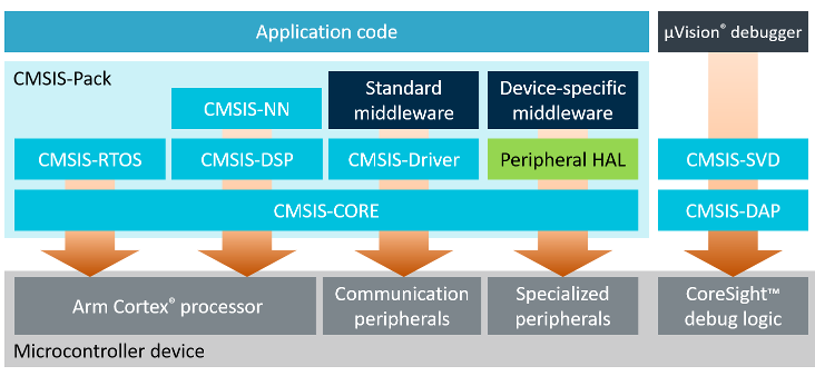
CMSIS Core
CMSIS-CORE – possibly the most important part – manages system startup, processor core access, and peripheral definitions for use in every embedded application.
CMSIS RTOS
The CMSIS RTOS specification provides a standard API for an RTOS. This is in effect a set of wrapper functions that translate the CMSIS RTOS API to the API of the specific RTOS that you are using (FreeRTOS, RTX RTOS .etc). The Keil RTX RTOS was the first RTOS to support the CMSIS RTOS API and it has been released as an open-source reference implementation.
CMSIS Driver
The CMSIS-Driver specification is a software API that describes peripheral driver interfaces for middleware stacks and user applications. The CMSIS-Driver API is designed to be generic and independent of a specific RTOS making it reusable across a wide range of supported microcontroller devices.
CMSIS-DSP
CMSIS-DSP allows developing a real-time digital signal processing (DSP) system being not as trivial as the DSP algorithms. The CMSIS-DSP library is a rich collection of DSP functions that are optimized for the various Cortex-M processor cores. CMSIS-DSP is widely used in the industry and also enables optimized C code generation from MATLAB®.
CMSIS SVD
CMSIS-SVD is included in CMSIS-Pack. It supports microcontroller detailed views to the device peripherals which displays the current register state with system view description (SVD) format.
CMSIS DAP
CMSIS-DAP is an integrated tool that uses the standardized interface to the Cortex debug access port (DAP) and is also used by several starters and development kits. Therefore, engineers do not need special debug units like ULINK, J-Link, or similar ones for basic board evaluation.
CMSIS packages include many other modern and specific libraries and middleware such as CMSIS-NN (neural networks and machine learning functions especially for IoT applications), and CMSIS-Zone (supports multiple cores MCUs, secured and non-secured programming) for most modern Cortex-M cores.
In this tutorial, we will focus on the CMSIS RTOS2.
CMSIS-RTOS2
CMSIS-RTOS2 is a generic API that is agnostic of the underlying RTOS kernel. Application programmers call CMSIS-RTOS2 API functions in the user code to ensure maximum portability from one RTOS to another. Middleware using CMSIS-RTOS2 API takes advantage of this approach by avoiding unnecessary porting efforts.
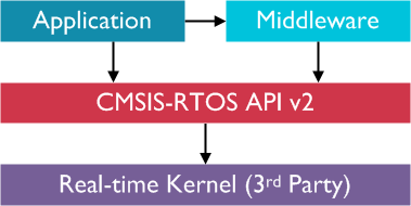 If you see the above picture, you can use any RTOS like FreeRTOS, RTX5 RTOS, .etc in the Real-time Kernel (3rd Party)’s place. So it will be useful for the developer to change from one RTOS to another RTOS easily. That’s why CMSIS is really useful.
In this tutorial, we will see only the APIs that we have used in the example.
CMSIS-RTOS2 APIs Used
Create a thread
The below API is used to create the thread.
osThreadNew()
The function osThreadNew starts a thread function by adding it to the list of active threads and sets it to state READY. Arguments for the thread function are passed using the parameter pointer *argument. When the priority of the created thread function is higher than the current RUNNING thread, the created thread function starts instantly and becomes the new RUNNING thread.
|
where,
It returns thread ID for reference by other functions or NULL in case of error. |
Example
static void thread1( void *arg )
{
  for (;;)                          //infinite for loop
  {
   //... your code
  }
}


osThreadNew(thread1, NULL, NULL);   // Create thread
There are many more APIs available. Please have a look at it here.
Initialize the system clock
SystemCoreClockUpdate()
There is one global variable called SystemCoreClock which is used to hold the system core clock value. So this function is used to update this SystemCoreClock whenever the clock is getting changed. This function must be called whenever the core clock is changed during program execution. The function evaluates the clock register settings and calculates the current core clock.
void SystemCoreClockUpdate( void )
Arg – None Return – None |
Initialize the Kernel
osKernelInitialize()
The function initializes the RTOS Kernel.
void SystemCoreClockUpdate( void )
Arg – None Return – None |
Start the Kernel
osKernelStart()
The function starts the RTOS kernel and begins thread switching. It will not return to its calling function in case of success. At least one initial thread (osThreadNew()) should be created prior osKernelStart(). And This function cannot be called from ISR.
|
Arg – None It returns
|
Delay
osDelay()
The function waits for a time period specified in the kernel ticks. The delayed thread is put into the BLOCKED state and a context switch occurs immediately. The thread is automatically put back to the READY state after the given amount of ticks has elapsed. If the thread will have the highest priority in the READY state it will be scheduled immediately.
This function cannot be called from ISR.
|
where,
It returns,
|
We have covered all the APIs that we have used in our below example source code. You can refer to other APIs here.
Example Programming
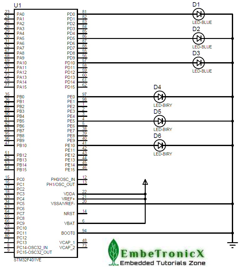
In this example project, LEDs have been connected to Port D and Port E. And we have created two tasks called LED_Blink_PortD and LED_Blink_PortE.
LED_Blink_PortD task will make the Port D LEDs blink in a 1-second delay and LED_Blink_PortE task will make the Port E LEDs blink in a 3-second delay.
Connection Diagram
- LEDs – PORT D and PORT E
Refer to the below image.
Source Code
You can find this complete source code on GitHub.
/***************************************************************************//**
*  \file       main.c
*
*  \details    LED Blinking using RTX CMSIS V2 RTOS
*
*  \author     EmbeTronicX
*
*  \Tested with Proteus
*
* *****************************************************************************/
#include "RTE_Components.h"
#include  CMSIS_device_header
#include "cmsis_os2.h"
#include "stm32f4xx.h"


/*
** This thread will turns ON and turns OFF the PORT-D LEDs with 1second delay.
**
**  Arguments:
**      arg  -> Argument of this thread. osThreadNew()'s 2nd arg has to come here.
**
*/
__NO_RETURN static void LED_Blink_PortD( void *arg )
{
  (void)arg;                            //unused variable
  //set Port D as output
  GPIOD->MODER = 0x55555555;

  for (;;)                              //infinite for loop
  {
    //Turn ON the LED of Port-D
    GPIOD->BSRR = 0x0000FFFF;
    osDelay(1000);                      //1sec delay
    //Turn OFF the LED of Port-D
    GPIOD->BSRR = 0xFFFF0000;
    osDelay(1000);                      //1sec delay
  }
}

/*
** This thread will turns ON and turns OFF the PORT-E LEDs with 3second delay.
**
**  Arguments:
**      arg  -> Argument of this thread. osThreadNew()'s 2nd arg has to come here.
**
*/
__NO_RETURN static void LED_Blink_PortE( void *arg )
{
  (void)arg;                            //unused variable
  //set Port E as output
  GPIOE->MODER = 0x55555555;
  for (;;)                              //infinite for loop
  {
    //Turn ON the LED of Port-E
    GPIOE->BSRR = 0x0000FFFF;
    osDelay(3000);                      //3sec delay
    //Turn OFF the LED of Port-E
    GPIOE->BSRR = 0xFFFF0000;
    osDelay(3000);                      //3sec delay
  }
}

/*
** main function
**
**  Arguments:
**      none
**
*/
int main (void)
{
  //Enable the AHB clock all GPIO Port-D
  SET_BIT(RCC->AHB1ENR, RCC_AHB1ENR_GPIODEN);
  //Enable the AHB clock all GPIO Port-E
  SET_BIT(RCC->AHB1ENR, RCC_AHB1ENR_GPIOEEN);

  // System Initialization
  SystemCoreClockUpdate();

  osKernelInitialize();                       // Initialize CMSIS-RTOS
  osThreadNew(LED_Blink_PortD, NULL, NULL);   // Create application main thread
  osThreadNew(LED_Blink_PortE, NULL, NULL);   // Create application main thread
  osKernelStart();                            // Start thread execution
  for (;;)
  {
    //Dummy infinite for loop.
  }
}
Output
Click here if you don’t see the output gif
If you don’t want to use RTOS, then you can refer to this GPIO tutorial for STM32 without RTOS.
Please read the other STM32 Tutorials.
You can also read the below tutorials.
Embedded Software | Firmware | Linux Devic Deriver | RTOS
Hi, I am a tech blogger and an Embedded Engineer. I am always eager to learn and explore tech-related concepts. And also, I wanted to share my knowledge with everyone in a more straightforward way with easy practical examples. I strongly believe that learning by doing is more powerful than just learning by reading. I love to do experiments. If you want to help or support me on my journey, consider sharing my articles, or Buy me a Coffee! Thank you for reading my blog! Happy learning!
