
This article is a continuation of the Series on STM32 MikroC Bootloader Development and carries the discussion on Bootloader design and implementation. The aim of this series is to provide easy and practical examples that anyone can understand. This post is Simple STM32 MikroC Custom Bootloader Development – Bootloader Tutorial Part 2. In this post, we are going to modify the bootloader that we have gotten from the MikroC Pro for ARM.
Table of Contents
Prerequisites
In this simple STM32 MikroC bootloader example, we will be using the concepts which have already been explained in the below-given tutorials. So I would request you to go through those tutorials first if you are not familiar with those topics.
If you want to develop the bootloader for STM32 with STM32CubeIDE, please refer to these tutorials.
Hardware Required
In this demo, we have used the below components and software.
We have our own EmbeTronicX Store called ChipTronicX. You can purchase the hardware from ChipTronicX.
|
|
|
- STM32F411 Microcontroller (You can use any other stm32 controller. But you need to set the proper flash address)
- MikroC Pro for ARM IDE
STM32 MikroC Custom Bootloader Development
We are assuming that you knew about the bootloader. If we are developing the bootloader using STM32CubeIDE, then we can easily develop it. Because we can change the interrupt vector table. So, the bootloader will be having different vector table, and the application or firmware will be having different bootloader. Once we jump from the bootloader to the application, we can change the vector table offset to the application or firmware vector table.
But in the MikroC Pro for ARM, we can’t change the address of the vector table. So, it will be always placed in the 0x08000000. Therefore, developing the bootloader is different in the MikroC Pro for ARM.
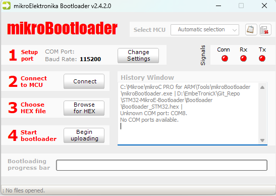
STM32 MikroC Pro for ARM Bootloader
In this post, we are going to take the bootloader source code from the MikroC. Once we flash the bootloader, we will have to use the MikroBootloader PC application to update the firmware or application.
Original MikroC Bootloader
MikroE has provided the example bootloader for the STM32F051R8 microcontroller. The code is given below.
USB_UART_BOOTLOADER.c
/*
 * Project name:
     USB_UART_Bootloader
 * Copyright:
     (c) MikroElektronika, 2018.
 * Revision History:
     - initial release;
 * Description:
     MCU flash. It is used, instead of programming tools, to
     load real program code into the MCU. Real program code can
     be passed from PC to bootloader by specific PC application
     (Bootloader Tool) over numerous communication interfaces.

     This bootloader communicates with PC over UART inteface
     by using mikroE bootloader protocol. It is designed to
     work in conjuction with mikroE's 'mikroBootloader'
     PC application.

 * Test configuration:
     MCU:             STM32F051R8
                      https://www.st.com/resource/en/datasheet/stm32f051r8.pdf
     Dev.Board:       MINI-M0 for STM32
                      https://www.mikroe.com/mini-stm32f0
     Oscillator:      48.000000
     Ext. Modules:    None
     SW:              mikroC PRO for ARM v6.0.0
                      https://www.mikroe.com/mikroc-arm
 * NOTES:
     - It's recommended not to alter the start address of the main().
       Otherwise, less space in ROM will be available for the
       application being bootloaded.
*/
////////////////////////////////////////////////////////////////////////////////
#include <built_in.h>
////////////////////////////////////////////////////////////////////////////////
#pragma orgall 0xEC00
#define BOOTLOADER_START_ADDR   0xEC00
#define START_PROGRAM_ADDR      0xFC00
////////////////////////////////////////////////////////////////////////////////
static char block[1024];
////////////////////////////////////////////////////////////////////////////////
void Start_Program() org START_PROGRAM_ADDR{

}
////////////////////////////////////////////////////////////////////////////////
unsigned short UART_Write_Loop(char send, char receive){
  unsigned int rslt = 0;

  while(1){
    Delay_5ms();
    UART_Write(send);
    Delay_5ms();

    rslt++;
    if (rslt == 0x0200)
      return 0;
    if(UART_Data_Ready()) {
      if(UART_Read() == receive)
        return 1;
    }
  }
}
////////////////////////////////////////////////////////////////////////////////
void FLASH_EraseWritePage(unsigned long address) {
  unsigned int i = 0;
  unsigned int dataToWrite;

  FLASH_ErasePage(address);

  for (i = 0; i < 512; i++)
  {
    dataToWrite = block[i * 2] | (block[i * 2 + 1] << 8);
    FLASH_Write_HalfWord(address + i*2, dataToWrite);
  }
}
////////////////////////////////////////////////////////////////////////////////
void Write_Begin(){
  unsigned int i;
  unsigned long* ptr;
  unsigned char appResetVector[16];
  unsigned long arm_m0_inst;
  unsigned int dataToWrite;

  //LDR R0, PC+X
  arm_m0_inst = 0x4800 + 1;

  appResetVector[0] = arm_m0_inst;
  appResetVector[1] = arm_m0_inst >> 8;

  //MOV SP, R0
  arm_m0_inst = 0x4685;

  appResetVector[2] = arm_m0_inst;
  appResetVector[3] = arm_m0_inst >> 8;

  //LDR R0, PC+Y
  arm_m0_inst = 0x4800 + 1;

  appResetVector[4] = arm_m0_inst;
  appResetVector[5] = arm_m0_inst >> 8;

  //BX R0
  arm_m0_inst = 0x4700;
  appResetVector[6] = arm_m0_inst;
  appResetVector[7] = arm_m0_inst >> 8;

  //SP
  appResetVector[8] = block[0];
  appResetVector[9] = block[1];
  appResetVector[10] = block[2];
  appResetVector[11] = block[3];

  //PC
  appResetVector[12] = block[4];
  appResetVector[13] = block[5];
  appResetVector[14] = block[6];
  appResetVector[15] = block[7];

  FLASH_ErasePage(START_PROGRAM_ADDR);

  for (i = 0; i < 8; i++)
  {
    dataToWrite = appResetVector[i * 2] | (appResetVector[i * 2 + 1] << 8);
    FLASH_Write_HalfWord(START_PROGRAM_ADDR + i*2, dataToWrite);
  }

  ptr = (unsigned long*)0x00000000;
  block[0] = LoWord(*ptr);
  block[1] = LoWord(*ptr) >> 8;
  block[2] = HiWord(*ptr);
  block[3] = HiWord(*ptr) >> 8;

  ptr++;

  block[4] = LoWord(*ptr);
  block[5] = LoWord(*ptr) >> 8;
  block[6] = HiWord(*ptr);
  block[7] = HiWord(*ptr) >> 8;
}
////////////////////////////////////////////////////////////////////////////////
void Start_Bootload(){
  unsigned int i = 0;
  char xx, yy;
  long j = 0;

  while (1) {
    if (i == 1024) {
      //--- If 256 words (1024 bytes) recieved then write to flash
      if (!j)
        Write_Begin();
      if (j < BOOTLOADER_START_ADDR) {
        FLASH_EraseWritePage(j);
      }

      i = 0;
      j += 0x400;
    }
    //--- Ask for yy
    UART_Write('y');
    while (!UART_Data_Ready()) ;
    //--- Read yy
    yy = UART_Read();
    //--- Ask for xx
    UART_Write('x');
    while (!UART_Data_Ready()) ;
    //--- Read xx
    xx = UART_Read();
    //--- Save xxyy in block[i]
    block[i++] = yy;
    block[i++] = xx;
  }
}
////////////////////////////////////////////////////////////////////////////////
void main() org BOOTLOADER_START_ADDR{
// Main program
  UART1_Init(115200);
  Delay_100ms();

  if (UART_Write_Loop('g','r')) {     // Send 'g' for ~5 sec, if 'r'
    Start_Bootload();                 //   received start bootload
  }
  else {
    Start_Program();                  //   else start program
  }
}
////////////////////////////////////////////////////////////////////////////////
Custom MikroC Bootloader Development
The above code won’t work for STM32F411. Because that STM32F0 has a different flash address. And also we don’t want to use their PC application. Instead, we are going to use our customized PC application. So, we need to modify the above bootloader code.
|
|
|
In the code, we are going to make two major changes.
- Flash address and the corresponding flash access APIs.
- Sending the Firmware or application size to the bootloader during the firmware update.
STM32 MikroC Bootloader Design
Please check the design and flow chart of the bootloader.
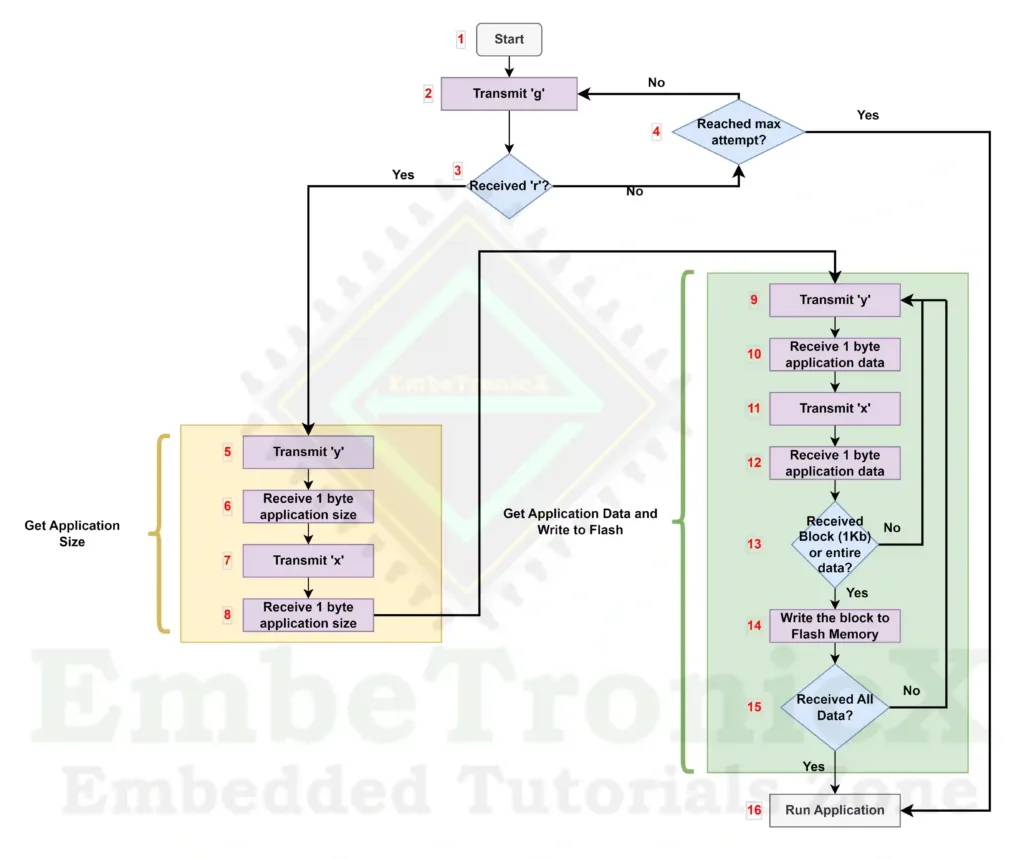
The bootloader process flow steps description is the following.
Block 1
The bootloader starts when the microcontroller power-up or resets.
- Goto Block 2.
Block 2
Transmit the character “g” through the USART to the host. In this example, we have used UART 1 for this data transfer.
|
|
|
- Goto Block 3.
Block 3
Check that we have received the character “r” from the host.
Block 4
Check that we have reached the maximum attempt. In this example, we set that count as 100.
- If it reached the maximum attempt, then go to Block 16.
- If it is not reached the maximum attempt, then go to Block 2.
Block 5
Till now we have got a response from the Host. Now we will receive the application size from the host. Now transmit the character ‘y’ to the host. Then go to Block 6.
Block 6
Receive the 1-byte data from the host. Then go to Block 7.
Block 7
Now transmit the character “x” to the host. Then go to Block 8.
|
|
|
Block 8
Receive the 1-byte data from the host. Now we can combine the bytes that we have received from Block 6 and Block 8 to get the application size. Then go to Block 9.
Block 9
Now we can receive the application data from the host. Transmit the character ‘y’ to the host. Then go to Block 10.
Block 10
Receive the 1-byte data from the host. Then go to Block 11.
Block 11
Now transmit the character “x” to the host. Then go to Block 8.
Block 12
Receive the 1-byte data from the host. Go to Block 13.
|
|
|
Block 13
Check that you have received all the data or the entire block of the data. In this example, we have set the block size as 1024 bytes.
Block 14
Write the data into the flash memory. Then go to Block 15.
Block 15
Check that you have received the entire application data.
Block 16
Now we have received the full data and written it into the flash memory or we did not receive any data from the host. Now, we can run our new or old application.
That’s it. Now we will implement the above concept in the code.
|
|
|
Connection
- LED – PC13 (Onboard LED)
- UART 1 (PA9, PA10) – For data transfer (115200Bps) (Use USB to Serial converter)
- UART 2 (PA2, PA3) – For Debug Prints (115200Bps) (Use USB to Serial converter)
Source code – STM32 MikroC Custom Bootloader
Bootloader Source Code
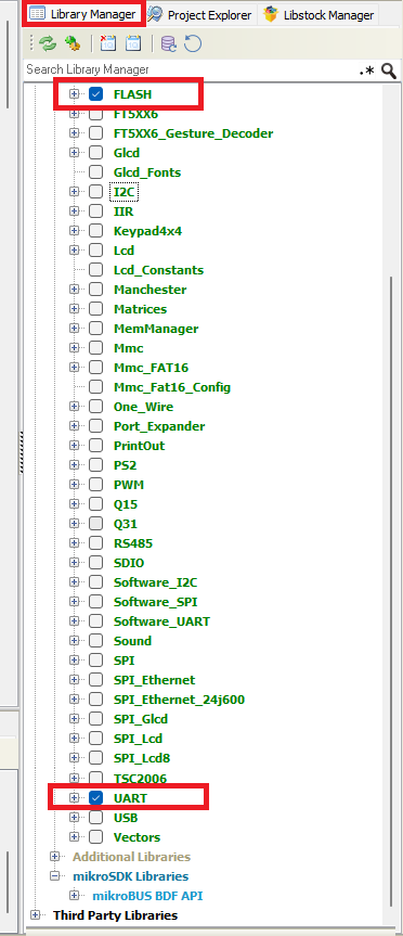
STM32F411 has 512KB flash memory. In that, we are going to give 256KB for the application and 256KB for the bootloader. So, the bootloader will start from 0x08040000. In the project’s Library manager, please enable FLASH and UART. please refer to the below image. Because we are going to use those.
Please check the below-modified bootloader source code. You can also find this code on GitHub.
#include "built_in.h"

///////////////////////////////////////////////////////////////////////////////
#pragma orgall 0x40000
#define BOOTLOADER_START_ADDR   0x40000
#define START_PROGRAM_ADDR      0x60000
#define FLASH_DEFAULT_ADDR      0x08000000

#define MAX_BLOCK_SIZE          ( 1024 )                  //1KB
#define MAX_APP_SIZE            ( 262144 )                //256KB
#define FIRMWARE_FILE_NAME      "App.bin"

#define UART_FIRMWARE_UPDATE

////////////////////////////////////////////////////////////////////////////////
void Write_Begin();
void FLASH_EraseWrite(unsigned long address);

////////////////////////////////////////////////////////////////////////////////
static char block[MAX_BLOCK_SIZE];

//LED Pin PC13
sbit LED at ODR13_GPIOC_ODR_bit;

////////////////////////////////////////////////////////////////////////////////
void Start_Program() org START_PROGRAM_ADDR
{

}

////////////////////////////////////////////////////////////////////////////////
unsigned short UART_Write_Loop(char send, char receive)
{
  unsigned int rslt = 0;

  while(1)
  {
    LED = 1;       // ON PC13
    Delay_ms(20);
    UART_Write(send);
    LED = 0;       // OFF PC13
    Delay_ms(20);

    rslt++;
    if (rslt == 0x64)           // 100 times
      return 0;
    if(UART_Data_Ready()) {
      if(UART_Read() == receive)
        return 1;
    }
  }
}
////////////////////////////////////////////////////////////////////////////////
void FLASH_EraseWrite(unsigned long address)
{
  unsigned int i = 0;
  unsigned int dataToWrite;

  FLASH_Unlock();

  for (i = 0; i < 512; i++)
  {
    dataToWrite = block[i * 2] | (block[i * 2 + 1] << 8);
    FLASH_Write_HalfWord( ( address + i*2 + + FLASH_DEFAULT_ADDR ), dataToWrite);
  }

  FLASH_Lock();
}
////////////////////////////////////////////////////////////////////////////////
void Write_Begin()
{
  unsigned int i;
  unsigned long* ptr;
  unsigned char appResetVector[16];
  unsigned long arm_m0_inst;
  unsigned int dataToWrite;

  //LDR R0, PC+X
  arm_m0_inst = 0x4800 + 1;

  appResetVector[0] = arm_m0_inst;
  appResetVector[1] = arm_m0_inst >> 8;

  //MOV SP, R0
  arm_m0_inst = 0x4685;

  appResetVector[2] = arm_m0_inst;
  appResetVector[3] = arm_m0_inst >> 8;

  //LDR R0, PC+Y
  arm_m0_inst = 0x4800 + 1;

  appResetVector[4] = arm_m0_inst;
  appResetVector[5] = arm_m0_inst >> 8;

  //BX R0
  arm_m0_inst = 0x4700;
  appResetVector[6] = arm_m0_inst;
  appResetVector[7] = arm_m0_inst >> 8;

  //SP
  appResetVector[8] = block[0];
  appResetVector[9] = block[1];
  appResetVector[10] = block[2];
  appResetVector[11] = block[3];

  //PC
  appResetVector[12] = block[4];
  appResetVector[13] = block[5];
  appResetVector[14] = block[6];
  appResetVector[15] = block[7];

  FLASH_Unlock();

  //Clear the 7th Sector (App Start Point)
  FLASH_EraseSector(_FLASH_SECTOR_7);

  for (i = 0; i < 8; i++)
  {
    dataToWrite = appResetVector[i * 2] | (appResetVector[i * 2 + 1] << 8);
    FLASH_Write_HalfWord( ( START_PROGRAM_ADDR + FLASH_DEFAULT_ADDR + i*2 ), dataToWrite);
  }

  FLASH_Lock();

  ptr = (unsigned long*)0x00000000;
  block[0] = LoWord(*ptr);
  block[1] = LoWord(*ptr) >> 8;
  block[2] = HiWord(*ptr);
  block[3] = HiWord(*ptr) >> 8;

  ptr++;

  block[4] = LoWord(*ptr);
  block[5] = LoWord(*ptr) >> 8;
  block[6] = HiWord(*ptr);
  block[7] = HiWord(*ptr) >> 8;

  //Erase Application area
  FLASH_EraseSector(_FLASH_SECTOR_0);
  FLASH_EraseSector(_FLASH_SECTOR_1);
  FLASH_EraseSector(_FLASH_SECTOR_2);
  FLASH_EraseSector(_FLASH_SECTOR_3);
  FLASH_EraseSector(_FLASH_SECTOR_4);
  FLASH_EraseSector(_FLASH_SECTOR_5);
}
////////////////////////////////////////////////////////////////////////////////
void Start_Bootload()
{
  unsigned int i = 0;
  char xx, yy;
  long j = 0x0;
  int k =0;
  unsigned int fw_size = 0;
  unsigned int curr_fw_size = 0;

  //Get firmware Size
  //--- Ask for yy
  UART_Write('y');
  while (!UART_Data_Ready()) ;
  //--- Read yy
  yy = UART_Read();
  //--- Ask for xx
  UART_Write('x');
  while (!UART_Data_Ready()) ;
  //--- Read xx
  xx = UART_Read();

  fw_size = yy | (xx << 8);

  while (1) {
    if( (i == MAX_BLOCK_SIZE) || ( curr_fw_size >= fw_size ) ) {
      //--- If 256 words (1024 bytes) recieved then write to flash
      if (!j)
        Write_Begin();
      if (j < BOOTLOADER_START_ADDR) {
        FLASH_EraseWrite(j);
      }

      i = 0;
      j += 0x400;

      for(k=0; k<MAX_BLOCK_SIZE; k++)
      {
        block[k] = 0;
      }
    }
    if( curr_fw_size >= fw_size )
    {
      LED = 1; // OFF PC13
      Delay_ms(2000);
      UART2_Write_Text("Jumping to Application!!!\r\n");
      Start_Program();
    }

    //--- Ask for yy
    UART_Write('y');
    while (!UART_Data_Ready()) ;
    //--- Read yy
    yy = UART_Read();
    //--- Ask for xx
    UART_Write('x');
    while (!UART_Data_Ready()) ;
    //--- Read xx
    xx = UART_Read();
    //--- Save xxyy in block[i]
    block[i++] = yy;
    block[i++] = xx;

    curr_fw_size += 2;
  }
}

void main()
{
  int i;

  GPIO_Digital_Output(&GPIOC_BASE,_GPIO_PINMASK_13);
  UART2_Init(115200);                                        //Debug Print UART

#ifdef UART_FIRMWARE_UPDATE
  UART2_Write_Text("!------Firmware Update using UART------!\r\n");
  UART1_Init(115200);
  if(UART_Write_Loop('g','r'))       // Send 'g' for ~5 sec, if 'r'
  {
    Start_Bootload();                //   received start bootload
  }
  else
#endif   //UART_FIRMWARE_UPDATE
  {
    UART2_Write_Text("Jumping to Application!!!\r\n");
    Start_Program();                  //   else start program
  }

  UART2_Write_Text("No Application Available...HALT!!!\r\n");
  while(1)
  {
  }
}
PC Tool Code
We have created the PC application source code using the C language. This tool is used to send the firmware or application from the PC to the STM32. You can also get the complete source code from GitHub.
/**************************************************

file: etx_ota_update_main.c
purpose:

compile with the command: gcc etx_ota_update_main.c RS232\rs232.c -IRS232 -Wall -Wextra -o2 -o etx_ota_app

**************************************************/
#include <stdint.h>
#include <stdlib.h>
#include <stdio.h>
#include <stdbool.h>

#ifdef _WIN32
#include <Windows.h>
#else
#include <unistd.h>
#endif

#include "rs232.h"

#define ETX_OTA_MAX_BLOCK_SIZE ( 1024 )
#define ETX_OTA_MAX_FW_SIZE    ( ETX_OTA_MAX_BLOCK_SIZE * 384 )

uint8_t APP_BIN[ETX_OTA_MAX_FW_SIZE];

void delay(uint32_t us)
{
#ifdef _WIN32
    //Sleep(ms);
    __int64 time1 = 0, time2 = 0, freq = 0;

    QueryPerformanceCounter((LARGE_INTEGER *) &time1);
    QueryPerformanceFrequency((LARGE_INTEGER *)&freq);

    do {
        QueryPerformanceCounter((LARGE_INTEGER *) &time2);
    } while((time2-time1) < us);
#else
    usleep(us);
#endif
}

int main(int argc, char *argv[])
{
  int comport;
  int bdrate   = 115200;       /* 115200 baud */
  char mode[]={'8','N','1',0}; /* *-bits, No parity, 1 stop bit */
  char bin_name[1024];
  int ex = 0;
  FILE *Fptr = NULL;

  do
  {
    if( argc <= 2 )
    {
      printf("Please feed the COM PORT number and the Application Image....!!!\n");
      printf("Example: .\\etx_ota_app.exe 8 ..\\..\\Application\\Debug\\Blinky.bin");
      ex = -1;
      break;
    }

    //get the COM port Number
    comport = atoi(argv[1]) -1;
    strcpy(bin_name, argv[2]);

    printf("Opening COM%d...\n", comport+1 );

    if( RS232_OpenComport(comport, bdrate, mode, 0) )
    {
      printf("Can not open comport\n");
      ex = -1;
      break;
    }

    printf("Opening Binary file : %s\n", bin_name);

    Fptr = fopen(bin_name,"rb");

    if( Fptr == NULL )
    {
      printf("Can not open %s\n", bin_name);
      ex = -1;
      break;
    }

    fseek(Fptr, 0L, SEEK_END);
    uint32_t app_size = ftell(Fptr);
    fseek(Fptr, 0L, SEEK_SET);

    printf("File size = %d\n", app_size);

    if( app_size > ETX_OTA_MAX_FW_SIZE )
    {
      printf("Application Size is more than the Maximum Size (%dKb)\n", ETX_OTA_MAX_FW_SIZE/ETX_OTA_MAX_BLOCK_SIZE);
      ex = -1;
      break;
    }

    //read the full image
    if( fread( APP_BIN, 1, app_size, Fptr ) != app_size )
    {
      printf("App/FW read Error\n");
      ex = -1;
      break;
    }

    unsigned char rec;

    printf("Waiting for OTA Start\n");
    do
    {
      RS232_PollComport( comport, &rec, 1);
    } while( rec != 'g' );

    printf("Sending r...\r\n");
    RS232_SendByte(comport, 'r');

    printf("Sending FW Size...\n");
    do
    {
      RS232_PollComport( comport, &rec, 1);
    } while( rec != 'y' );

    if( RS232_SendByte(comport, (uint8_t)app_size))
    {
      //some data missed.
      printf("OTA DATA : Send Err\n");
      ex = -1;
      break;
    }

    do
    {
      RS232_PollComport( comport, &rec, 1);
    } while( rec != 'x' );

    if( RS232_SendByte(comport, (uint8_t)(app_size >> 8)) )
    {
      //some data missed.
      printf("OTA DATA : Send Err\n");
      ex = -1;
      break;
    }

    printf("Sending Data...\n");

    for( uint32_t i = 0; i < app_size;)
    {
      do
      {
        RS232_PollComport( comport, &rec, 1);
      } while( rec != 'y' );

      if( RS232_SendByte(comport, APP_BIN[i++]) )
      {
        //some data missed.
        printf("OTA DATA : Send Err\n");
        ex = -1;
        break;
      }

      do
      {
        RS232_PollComport( comport, &rec, 1);
      } while( rec != 'x' );

      if( RS232_SendByte(comport, APP_BIN[i++]) )
      {
        //some data missed.
        printf("OTA DATA : Send Err\n");
        ex = -1;
        break;
      }
      if( ( i % ETX_OTA_MAX_BLOCK_SIZE ) == 0 )
      {
        printf("Block %d Transmitted...\r\n", i/ETX_OTA_MAX_BLOCK_SIZE);
      }

    }

    if( ex < 0 )
    {
      break;
    }

  } while (false);

  if(Fptr)
  {
    fclose(Fptr);
  }

  if( ex < 0 )
  {
    printf("OTA ERROR\n");
  }
  return(ex);
}
Application Source Code
We have created a simple application that toggles the PC13 LED every 1 second for testing. You can get the complete source code from GitHub.
#include <built_in.h>

#define LED_PIN (1<<13)

void main()
{
  GPIO_Digital_Output(&GPIOC_BASE, _GPIO_PINMASK_13); // Set PC13 as digital output

  while(1) {
    GPIOC_ODR |= LED_PIN; // ON PC13
    Delay_ms(1000);
    GPIOC_ODR &= (~LED_PIN); // OFF PC13
    Delay_ms(1000);
  }
}
That’s it. We have created the project. You can get the entire project from GitHub.
|
|
|
Testing the STM32 MikroC Custom Bootloader
- Flash the Bootloader to the STM32.
- You should see the LED blinking fastly for 100 times. Then you should see the below prints.
!------Firmware Update using UART------!
Jumping to Application!!!
No Application Available…HALT!!!
- Yes, we don’t have the application. That’s why we are seeing this print.
- Now we will send the application using the PC Tool that we have created.
- Open the command prompt in the host application directory and build the host application using the below command.
gcc etx_ota_update_main.c RS232\rs232.c -IRS232 -Wall -Wextra -o2 -o etx_ota_app
- Then run the application with two arguments. (The first argument is COMPORT number, and the second argument is the Application binary path). See the example below.
.\etx_ota_app.exe 8 ..\Application\Application_STM32.bin
- Now the PC will be waiting for the Start command from the STM32. You should see the below prints in the command prompt.
D:\EmbeTronicX\Git_Repo\STM32-MikroE-Bootloader\PcTool>.\etx_ota_app.exe 8 ..\Application\Application_STM32.bin
Opening COM8...
Opening Binary file : ..\Application\Application_STM32.bin
File size = 2496
Waiting for OTA Start
- Now, reset the STM32 Board. It should update the new application and the LED should be blinking every 1 second. You should get the below prints.
PcTool Prints
D:\EmbeTronicX\Git_Repo\STM32-MikroE-Bootloader\PcTool>.\etx_ota_app.exe 8 ..\Application\Application_STM32.bin
Opening COM8…
Opening Binary file : ..\Application\Application_STM32.bin
File size = 2496
Waiting for OTA Start
Sending r…
Sending FW Size…
Sending Data…
Block 1 Transmitted…
Block 2 Transmitted…
UART Prints
!------Firmware Update using UART------!
Jumping to Application!!!
No Application Available…HALT!!!
€!------Firmware Update using UART------!
Jumping to Application!!!
We hope you have learned something new today. In our next post, we will see how to update the application from the SD card in the MikroC Pro for ARM.
|
|
|
You can also read the below tutorials.
Embedded Software | Firmware | Linux Devic Deriver | RTOS
Hi, I am a tech blogger and an Embedded Engineer. I am always eager to learn and explore tech-related concepts. And also, I wanted to share my knowledge with everyone in a more straightforward way with easy practical examples. I strongly believe that learning by doing is more powerful than just learning by reading. I love to do experiments. If you want to help or support me on my journey, consider sharing my articles, or Buy me a Coffee! Thank you for reading my blog! Happy learning!
