This is the Series of tutorials on the STM32 Microcontroller. The aim of this series is to provide easy and practical examples that anyone can understand. In our last article, we have seen complete detailed information of the DMA and STM32 DMA for memory-to-memory transfer example. In this tutorial, we are going to see STM32 UART DMA – Peripheral to Memory data transfer.
Table of Contents
Hardware Required
STM32 UART DMA – Part 2 (Peripheral to Memory Transfer)
There are multiple ways that we can receive data from the UART.
- Polling method – Checking continuously for the arrival of data.
- Interrupt method – When the data arrives, the interrupt will be triggered.
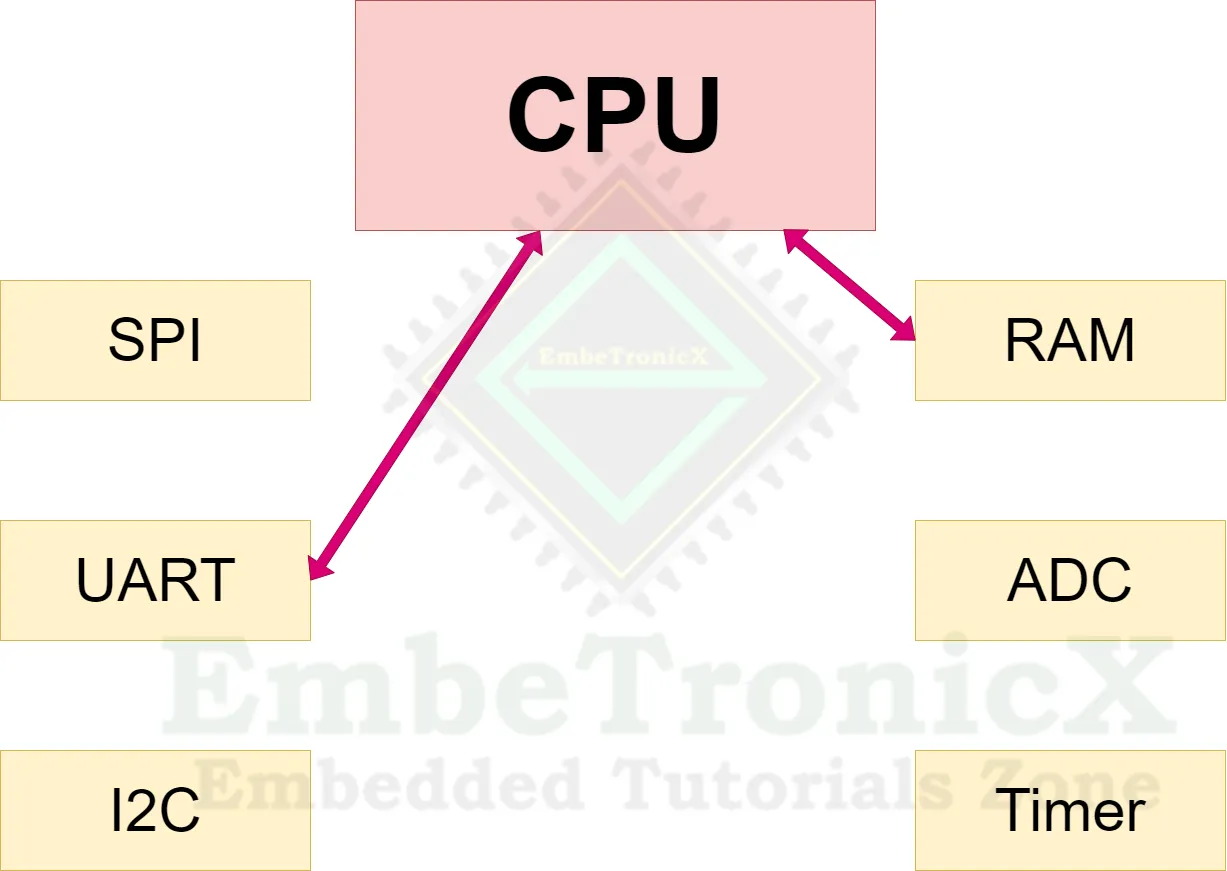
In both methods, the CPU is involved in the transaction like the below image. The data has to go through the CPU.
If we use the DMA method, the CPU is not involved in the data transfer. Refer to the below image.
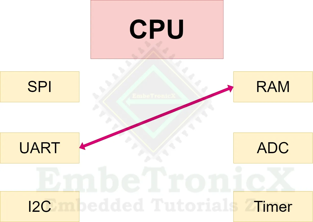
DMA also works like an interrupt mode. But the only difference is that the CPU is not involved.
|
|
|
STM32 UART DMA Example
Project Creation
Create the new STM32 project in STM32CubeIDE.
Note: This project was set up with STM32CubeMx V6.6.1 using STM32Cube FW_F7 V1.17.1.
In the STM32F767Zi Nucleo board, USART3 is available as a virtual COM Port. So, we don’t need any external connector. So we can use USART3.
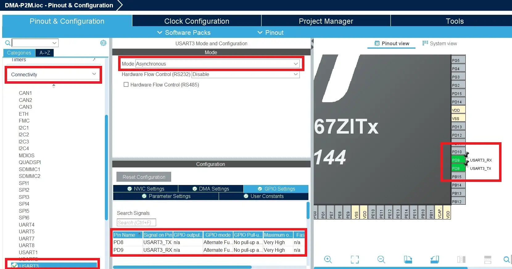
In the .ioc file, Click “Connectivity” –> “USART3“. Select Mode as Asynchronous. Then configure the PD9 and PD8 for USART3. Refer to the below image. The baud rate is 115200.
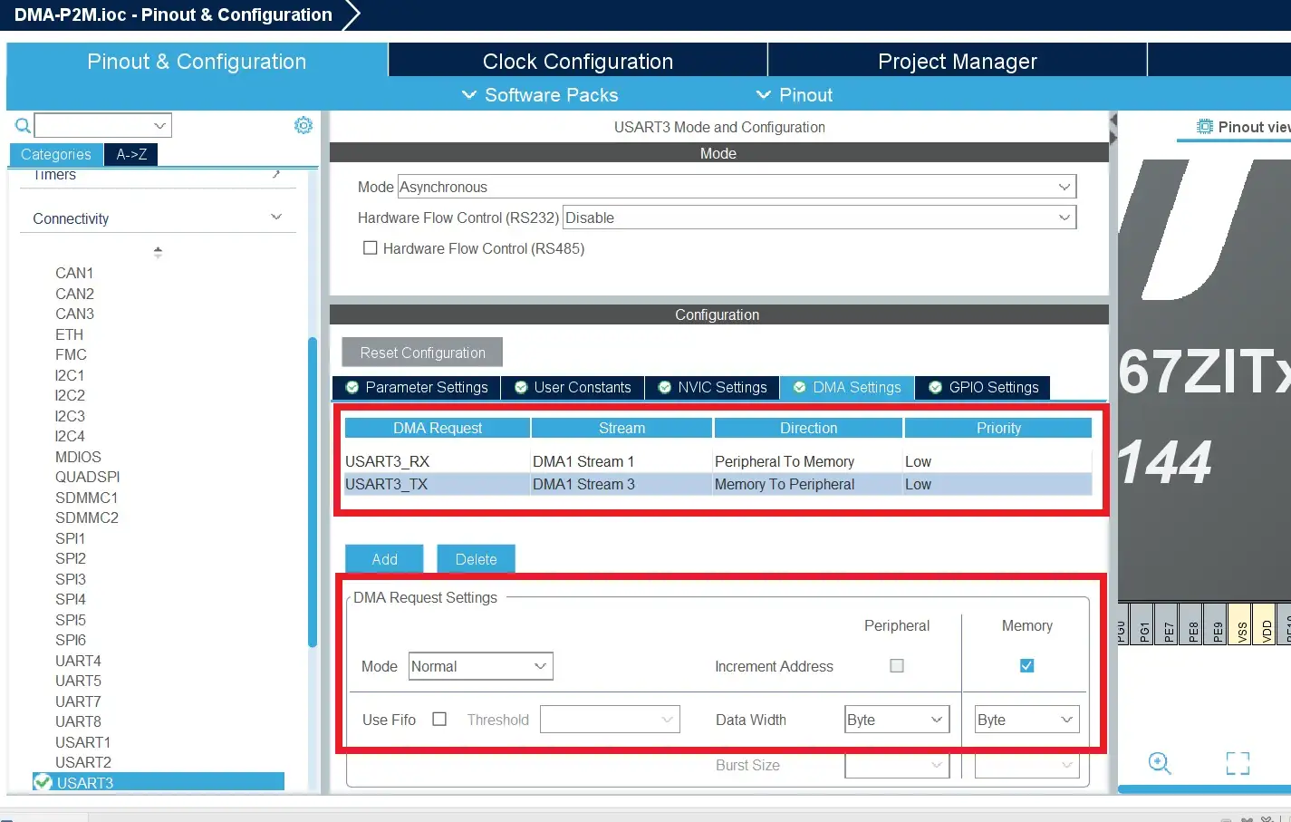
Then click DMA Settings and Enable the DMA Request for Both TX and RX. Because we are going to use DMA for Peripheral to Memory and Memory to Peripheral data transfer. Refer to the below image.
|
|
|
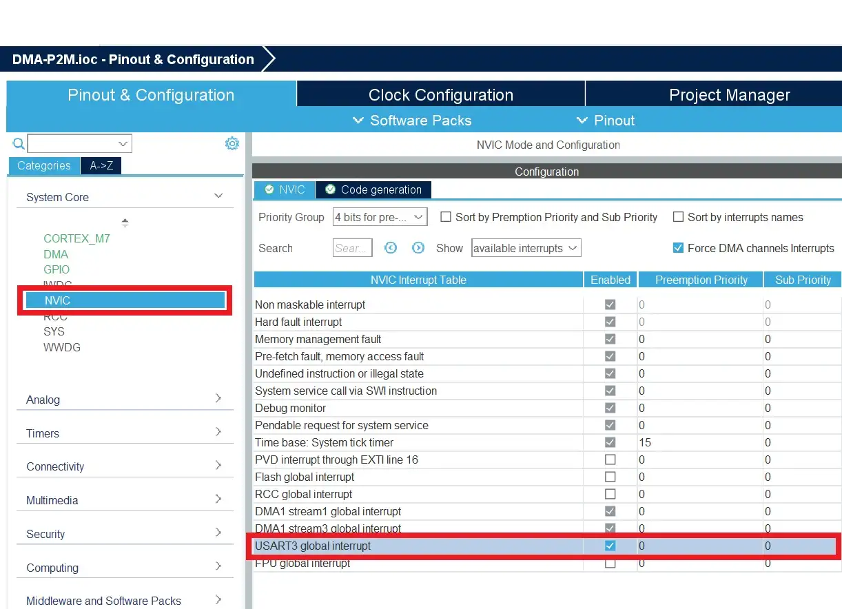
Now, we will enable the USART3 Interrupt. Click NVIC –> USART3 global interrupt. Check the below image.
Save the .ioc file and generate the code.
Source Code
[You can get the complete project source code on GitHub]
In this example, we are going to receive 100 bytes of data from the UART and transmit the same data back to the same UART. Both UART to Memory and Memory to UART are going to happen using the DMA. So, we need to enable both TX and RX DMA Requests.
Note: Whenever you are adding your code, you must include your code between the USER CODE BEGIN and USER CODE END. If you add your code anywhere else, then it will be removed when you regenerate the code.
|
|
|
First, let’s create the buffer (RX_BUF) to hold the 100 bytes of data.
/* USER CODE BEGIN 0 */
uint8_t RX_BUF[100];
/* USER CODE END 0 */
Then we will start the DMA Request for UART RX using the HAL_UART_Receive_DMA(). Add this function to the main function.
  /* USER CODE BEGIN 2 */
  HAL_UART_Receive_DMA(&huart3, RX_BUF, sizeof(RX_BUF));
  /* USER CODE END 2 */
This function starts the DMA. When the data is received from the UART, the DMA controller will write the data to the RX_BUF buffer. Once it receives the 100 bytes (since the size is set to sizeof(RX_BUF)), it will call the function named HAL_UART_RxCpltCallback(). This function is defined weak function. So, we can define the same function in our file (without changing the name).
Once that HAL_UART_RxCpltCallback() function gets called, which means we received 100 bytes. In that function, we are again transmitting the data to the same UART using DMA. Then again starting the receive DMA. Check the below code.
/* USER CODE BEGIN 4 */
void HAL_UART_RxCpltCallback(UART_HandleTypeDef *huart)
{
	/* Re Transmit the data */
	HAL_UART_Transmit_DMA(&huart3, RX_BUF, sizeof(RX_BUF));

	/* Start the DMA again for Rx */
	HAL_UART_Receive_DMA(&huart3, RX_BUF, sizeof(RX_BUF));
}
/* USER CODE END 4 */
Note: In this example, we have used the DMA Request mode as Normal Mode. That’s why we are calling this HAL_UART_Receive_DMA() function again whenever we get the complete data (inside the HAL_UART_RxCpltCallback function). If you use Circular Mode, then we do not need to call this HAL_UART_Receive_DMA() function inside the HAL_UART_RxCpltCallback function. Because it will treat that buffer as a circular buffer.
|
|
|
Full Source Code – STM32 UART DMA
main.c
/* USER CODE BEGIN Header */
/**
  ******************************************************************************
  * @file           : main.c
  * @brief          : Main program body
  ******************************************************************************
  * @attention
  *
  * Copyright (c) 2023 STMicroelectronics.
  * All rights reserved.
  *
  * This software is licensed under terms that can be found in the LICENSE file
  * in the root directory of this software component.
  * If no LICENSE file comes with this software, it is provided AS-IS.
  *
  ******************************************************************************
  */
/* USER CODE END Header */
/* Includes ------------------------------------------------------------------*/
#include "main.h"

/* Private includes ----------------------------------------------------------*/
/* USER CODE BEGIN Includes */

/* USER CODE END Includes */

/* Private typedef -----------------------------------------------------------*/
/* USER CODE BEGIN PTD */

/* USER CODE END PTD */

/* Private define ------------------------------------------------------------*/
/* USER CODE BEGIN PD */

/* USER CODE END PD */

/* Private macro -------------------------------------------------------------*/
/* USER CODE BEGIN PM */

/* USER CODE END PM */

/* Private variables ---------------------------------------------------------*/

UART_HandleTypeDef huart3;
DMA_HandleTypeDef hdma_usart3_rx;
DMA_HandleTypeDef hdma_usart3_tx;

/* USER CODE BEGIN PV */

/* USER CODE END PV */

/* Private function prototypes -----------------------------------------------*/
void SystemClock_Config(void);
static void MPU_Config(void);
static void MX_GPIO_Init(void);
static void MX_DMA_Init(void);
static void MX_USART3_UART_Init(void);
/* USER CODE BEGIN PFP */

/* USER CODE END PFP */

/* Private user code ---------------------------------------------------------*/
/* USER CODE BEGIN 0 */
uint8_t RX_BUF[100];
/* USER CODE END 0 */

/**
  * @brief  The application entry point.
  * @retval int
  */
int main(void)
{
  /* USER CODE BEGIN 1 */

  /* USER CODE END 1 */

  /* MPU Configuration--------------------------------------------------------*/
  MPU_Config();

  /* MCU Configuration--------------------------------------------------------*/

  /* Reset of all peripherals, Initializes the Flash interface and the Systick. */
  HAL_Init();

  /* USER CODE BEGIN Init */

  /* USER CODE END Init */

  /* Configure the system clock */
  SystemClock_Config();

  /* USER CODE BEGIN SysInit */

  /* USER CODE END SysInit */

  /* Initialize all configured peripherals */
  MX_GPIO_Init();
  MX_DMA_Init();
  MX_USART3_UART_Init();
  /* USER CODE BEGIN 2 */
  HAL_UART_Receive_DMA(&huart3, RX_BUF, sizeof(RX_BUF));
  /* USER CODE END 2 */

  /* Infinite loop */
  /* USER CODE BEGIN WHILE */
  while (1)
  {
    /* USER CODE END WHILE */

    /* USER CODE BEGIN 3 */
  }
  /* USER CODE END 3 */
}

/**
  * @brief System Clock Configuration
  * @retval None
  */
void SystemClock_Config(void)
{
  RCC_OscInitTypeDef RCC_OscInitStruct = {0};
  RCC_ClkInitTypeDef RCC_ClkInitStruct = {0};

  /** Configure the main internal regulator output voltage
  */
  __HAL_RCC_PWR_CLK_ENABLE();
  __HAL_PWR_VOLTAGESCALING_CONFIG(PWR_REGULATOR_VOLTAGE_SCALE3);

  /** Initializes the RCC Oscillators according to the specified parameters
  * in the RCC_OscInitTypeDef structure.
  */
  RCC_OscInitStruct.OscillatorType = RCC_OSCILLATORTYPE_HSI;
  RCC_OscInitStruct.HSIState = RCC_HSI_ON;
  RCC_OscInitStruct.HSICalibrationValue = RCC_HSICALIBRATION_DEFAULT;
  RCC_OscInitStruct.PLL.PLLState = RCC_PLL_NONE;
  if (HAL_RCC_OscConfig(&RCC_OscInitStruct) != HAL_OK)
  {
    Error_Handler();
  }

  /** Initializes the CPU, AHB and APB buses clocks
  */
  RCC_ClkInitStruct.ClockType = RCC_CLOCKTYPE_HCLK|RCC_CLOCKTYPE_SYSCLK
                              |RCC_CLOCKTYPE_PCLK1|RCC_CLOCKTYPE_PCLK2;
  RCC_ClkInitStruct.SYSCLKSource = RCC_SYSCLKSOURCE_HSI;
  RCC_ClkInitStruct.AHBCLKDivider = RCC_SYSCLK_DIV1;
  RCC_ClkInitStruct.APB1CLKDivider = RCC_HCLK_DIV1;
  RCC_ClkInitStruct.APB2CLKDivider = RCC_HCLK_DIV1;

  if (HAL_RCC_ClockConfig(&RCC_ClkInitStruct, FLASH_LATENCY_0) != HAL_OK)
  {
    Error_Handler();
  }
}

/**
  * @brief USART3 Initialization Function
  * @param None
  * @retval None
  */
static void MX_USART3_UART_Init(void)
{

  /* USER CODE BEGIN USART3_Init 0 */

  /* USER CODE END USART3_Init 0 */

  /* USER CODE BEGIN USART3_Init 1 */

  /* USER CODE END USART3_Init 1 */
  huart3.Instance = USART3;
  huart3.Init.BaudRate = 115200;
  huart3.Init.WordLength = UART_WORDLENGTH_8B;
  huart3.Init.StopBits = UART_STOPBITS_1;
  huart3.Init.Parity = UART_PARITY_NONE;
  huart3.Init.Mode = UART_MODE_TX_RX;
  huart3.Init.HwFlowCtl = UART_HWCONTROL_NONE;
  huart3.Init.OverSampling = UART_OVERSAMPLING_16;
  huart3.Init.OneBitSampling = UART_ONE_BIT_SAMPLE_DISABLE;
  huart3.AdvancedInit.AdvFeatureInit = UART_ADVFEATURE_NO_INIT;
  if (HAL_UART_Init(&huart3) != HAL_OK)
  {
    Error_Handler();
  }
  /* USER CODE BEGIN USART3_Init 2 */

  /* USER CODE END USART3_Init 2 */

}

/**
  * Enable DMA controller clock
  */
static void MX_DMA_Init(void)
{

  /* DMA controller clock enable */
  __HAL_RCC_DMA1_CLK_ENABLE();

  /* DMA interrupt init */
  /* DMA1_Stream1_IRQn interrupt configuration */
  HAL_NVIC_SetPriority(DMA1_Stream1_IRQn, 0, 0);
  HAL_NVIC_EnableIRQ(DMA1_Stream1_IRQn);
  /* DMA1_Stream3_IRQn interrupt configuration */
  HAL_NVIC_SetPriority(DMA1_Stream3_IRQn, 0, 0);
  HAL_NVIC_EnableIRQ(DMA1_Stream3_IRQn);

}

/**
  * @brief GPIO Initialization Function
  * @param None
  * @retval None
  */
static void MX_GPIO_Init(void)
{
/* USER CODE BEGIN MX_GPIO_Init_1 */
/* USER CODE END MX_GPIO_Init_1 */

  /* GPIO Ports Clock Enable */
  __HAL_RCC_GPIOD_CLK_ENABLE();

/* USER CODE BEGIN MX_GPIO_Init_2 */
/* USER CODE END MX_GPIO_Init_2 */
}

/* USER CODE BEGIN 4 */
void HAL_UART_RxCpltCallback(UART_HandleTypeDef *huart)
{
	/* Re Transmit the data */
	HAL_UART_Transmit_DMA(&huart3, RX_BUF, sizeof(RX_BUF));

	/* Start the DMA again */
	HAL_UART_Receive_DMA(&huart3, RX_BUF, sizeof(RX_BUF));
}
/* USER CODE END 4 */

/* MPU Configuration */

void MPU_Config(void)
{
  MPU_Region_InitTypeDef MPU_InitStruct = {0};

  /* Disables the MPU */
  HAL_MPU_Disable();

  /** Initializes and configures the Region and the memory to be protected
  */
  MPU_InitStruct.Enable = MPU_REGION_ENABLE;
  MPU_InitStruct.Number = MPU_REGION_NUMBER0;
  MPU_InitStruct.BaseAddress = 0x0;
  MPU_InitStruct.Size = MPU_REGION_SIZE_4GB;
  MPU_InitStruct.SubRegionDisable = 0x87;
  MPU_InitStruct.TypeExtField = MPU_TEX_LEVEL0;
  MPU_InitStruct.AccessPermission = MPU_REGION_NO_ACCESS;
  MPU_InitStruct.DisableExec = MPU_INSTRUCTION_ACCESS_DISABLE;
  MPU_InitStruct.IsShareable = MPU_ACCESS_SHAREABLE;
  MPU_InitStruct.IsCacheable = MPU_ACCESS_NOT_CACHEABLE;
  MPU_InitStruct.IsBufferable = MPU_ACCESS_NOT_BUFFERABLE;

  HAL_MPU_ConfigRegion(&MPU_InitStruct);
  /* Enables the MPU */
  HAL_MPU_Enable(MPU_PRIVILEGED_DEFAULT);

}

/**
  * @brief  This function is executed in case of error occurrence.
  * @retval None
  */
void Error_Handler(void)
{
  /* USER CODE BEGIN Error_Handler_Debug */
  /* User can add his own implementation to report the HAL error return state */
  __disable_irq();
  while (1)
  {
  }
  /* USER CODE END Error_Handler_Debug */
}

#ifdef  USE_FULL_ASSERT
/**
  * @brief  Reports the name of the source file and the source line number
  *         where the assert_param error has occurred.
  * @param  file: pointer to the source file name
  * @param  line: assert_param error line source number
  * @retval None
  */
void assert_failed(uint8_t *file, uint32_t line)
{
  /* USER CODE BEGIN 6 */
  /* User can add his own implementation to report the file name and line number,
     ex: printf("Wrong parameters value: file %s on line %d\r\n", file, line) */
  /* USER CODE END 6 */
}
#endif /* USE_FULL_ASSERT */
Demo
The code is ready. Build the code and flash it.
I have a text file (Data.txt) that has 100 bytes of data including a line feed (\n). The data is like below.
0123456789abcdefghij0123456789abcdefghij0123456789abcdefghij0123456789abcdefghij0123456789abcdefghi
I am going to send this file using the Tera Term terminal. Check the video below for output.
See, the 100-byte data has been transferred to the RX_BUF buffer using USART RX. Then the same data was transmitted using the USART TX DMA. That’s why we are seeing that data in the terminal.
|
|
|
Please read the other STM32 Tutorials.
In our next article, we will connect the pendrive to the STM32 Board – STM32 USB Host MSC Example.
You can read the below tutorials.
Embedded Software | Firmware | Linux Devic Deriver | RTOS
Hi, I am a tech blogger and an Embedded Engineer. I am always eager to learn and explore tech-related concepts. And also, I wanted to share my knowledge with everyone in a more straightforward way with easy practical examples. I strongly believe that learning by doing is more powerful than just learning by reading. I love to do experiments. If you want to help or support me on my journey, consider sharing my articles, or Buy me a Coffee! Thank you for reading my blog! Happy learning!
