This is the Series of tutorials on the STM32 Microcontroller. The aim of this series is to provide easy and practical examples that anyone can understand. In our last article, we have seen STM32 Ethernet Tutorial using CGI – HTTP Server Part 2. In this article, we are going to discuss STM32 DMA – Direct Memory Access.
Table of Contents
Hardware Required
STM32 DMA Tutorial – Direct Memory Access Introduction
Before starting with the STM32 DMA, we should know the basics of DMA (Direct Memory Access).
What is DMA (Direct Memory Access)?
Before explaining about DMA, we will see one real-life example. Assume that you are a husband, and you have one wife, and one child in your family. In your child’s school, there is a parent-teacher meeting scheduled. But if you go to that meeting, you have to spend the whole day In school, which will affect your other work. But you need to do that other work also. There is no excuse. So, what you can do? You can ask your wife to go to school and you can concentrate on your work. So, your intervention is not required on that day. Your wife will take care of that parent-teacher meeting. So, there are two things. One is you can concentrate on the other work, and the second is that parent-teacher meetings also happen on time.
I know this example might not be a great one. You might have many questions in this example like why should only women go to school? Can’t women have other work? Nothing is more important than the parent-teacher meeting. I am sorry for that, and this is just an example.
Now we will go to DMA. DMA stands for Direct Memory Access. The name itself is self-explanatory. Using DMA we can access the memory directly without CPU intervention. In other words, it transfers data between different devices or memory regions without involving the CPU.
|
|
|
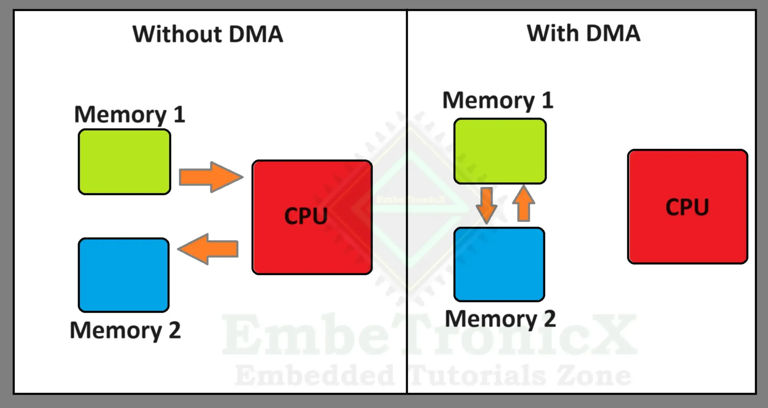
Check the below image. In that, we have two memories called memory 1 and memory 2. If we don’t have the DMA, then the read-write from/to memories needs the CPU’s help. So, the time taken for that process will be more, and also CPU is occupied for this operation. If we have DMA, then the DMA controller will take care of that process and the CPU can do the other process. So, the memory can be accessed without the CPU involvement, and this process takes less time.
Not only memory to memory but even the DMA data transfer can be done between peripherals and memory.
For example, let us consider another example. We have connected the microphone to the microcontroller and we need to capture the audio data through an I2S peripheral. You know that audio data is huge and it will be coming continuously. So, if the CPU is receiving the data from I2S and copying it to the local memory, then the other process will be affected as the data is huge. So, if we have DMA, then we can configure it to store the audio data directly in the memory without disturbing the CPU. So, the CPU will be doing other work instead of just copying the data to the local memory.
Why do we need DMA in microcontrollers?
We need to have a DMA in the microcontroller for many reasons, such as:
- To improve the performance and efficiency of data transfer between peripherals and memory, without involving the CPU. This frees up the CPU for other tasks and reduces the overhead and latency of interrupt-driven I/O.
- To reduce the power consumption and heat dissipation of the system, as the CPU can enter a low-power mode or sleep mode while the DMA controller handles the data transfer.
- To support high-speed devices and applications that require large amounts of data to be transferred quickly and reliably, such as audio, video, networking, or encryption.
- To simplify the device driver development and maintenance, as the DMA controller abstracts the details of the hardware and the memory management, and provides a standard interface for the device driver to use.
DMA in STM32
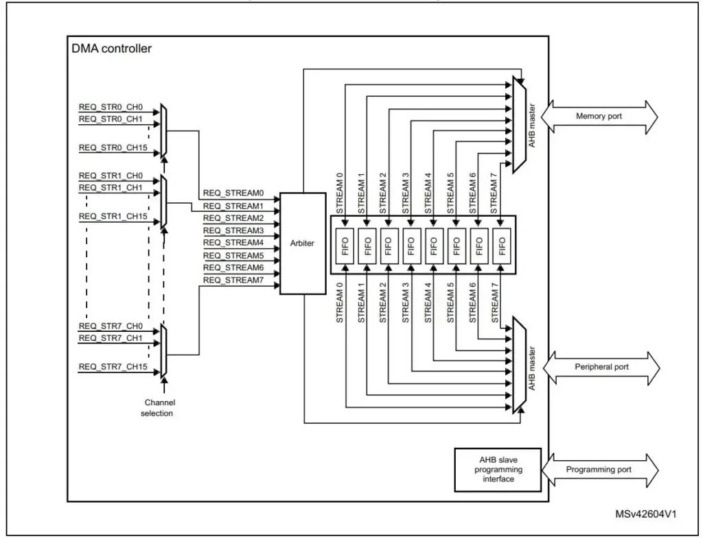
In this article, we are going to use the STM32F767Zi microcontroller. But these concepts are the same in STM32F4, STM32F2, and STM32F7. The DMA controller has a powerful dual AHB master bus architecture with independent FIFO to optimize the bandwidth of the system, based on a complex bus matrix architecture. One AHB master bus is dedicated to memory access and another AHB master bus is dedicated to the peripheral access.
|
|
|
STM32 DMA Features
- STM32F767Zi has two DMA Controllers called as DMA1 and DMA2. Each DMA controller has 8 streams, and a total of 16 streams.
- Each stream can have up to 16 channels (requests) in total. Each DMA controller has an arbiter for handling the priority between DMA requests.
- It has a four-word depth of 32 FIFO memory buffers per stream. These FIFO buffers can be used in FIFO mode or Direct mode.
- Priorities between DMA stream requests are software-programmable (4 levels consisting of very high, high, medium, low) or hardware in case of equality (for example, request 0 has priority over request 1).
- The number of data items to be transferred can be managed either by the DMA controller or by the peripheral. If we use DMA to control the number of items, then it can support a maximum of 65535 items. If we use peripherals to control, the number of items are unknown and controlled by the source or the destination peripheral that signals the end of the transfer by hardware.
- Each stream supports circular buffer management.
- There are 5 event flags available (DMA half transfer, DMA transfer complete, DMA transfer error, DMA FIFO error, direct mode error) logically ORed together in a single interrupt request for each stream.
- Incrementing or non-incrementing addressing for source and destination.
The block diagram of the STM32F7 DMA is given below.
STM32 DMA Data Transactions
A DMA transaction consists of a sequence of a given number of data transfers. The number of data items to be transferred and their width (8-bit, 16-bit, or 32-bit) are software-programmable.
Each DMA transfer consists of three operations:
- First, the data needs to be loaded from the peripheral data register or some location in memory. And it should be addressed through the
DMA_SxPAR(In case of peripheral) orDMA_SxM0AR(In case of memory) register. - Then the storage of the data loaded to the peripheral data register or a location in memory addressed through the
DMA_SxPARorDMA_SxM0ARregister. - Finally, a post-decrement of the
DMA_SxNDTRregister, containing the number of transactions that still have to be performed.
After an event, the peripheral sends a request signal to the DMA controller. The DMA controller serves the request depending on the channel priorities. As soon as the DMA controller accesses the peripheral, an Acknowledge signal is sent to the peripheral by the DMA controller. The peripheral releases its request as soon as it gets the Acknowledge signal from the DMA controller. Once the request has been deasserted by the peripheral, the DMA controller releases the Acknowledge signal. If there are more requests, the peripheral can initiate the next transaction.
DMA Data Transfer Modes
DMA is capable of performing three different transfer modes as given below:
|
|
|
- Memory to Memory
- Memory to Peripheral
- Peripheral to Memory
In this article, we will focus on memory-to-memory data transfer using the DMA.
Memory to Memory data transfer using DMA in STM32
Project Creation
Create the new STM32 project in STM32CubeIDE.
Note: This project was set up with STM32CubeMx V6.6.1 using STM32Cube FW_F7 V1.17.1.
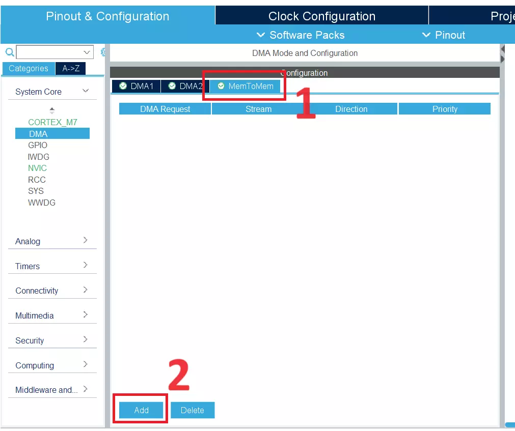
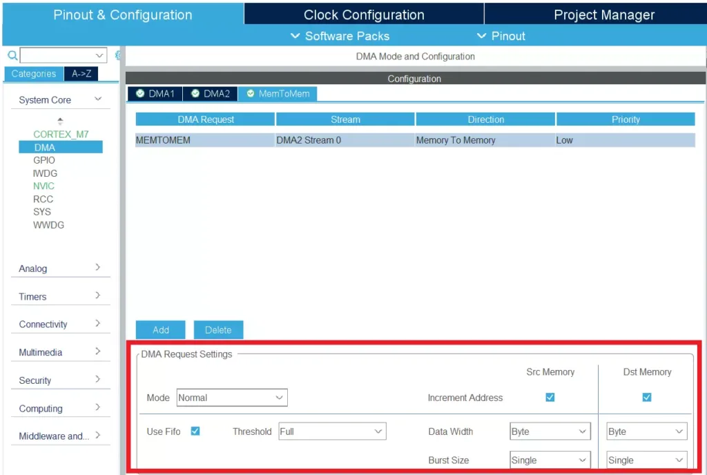
In the .ioc file, Click “System Core” –> “DMA“. Select MemToMem and click the Add button. Refer to the below image.
Note: Only DMA2 can do memory-to-memory transfer, in this mode, the circular and direct modes are not allowed.
|
|
|
In the DMA Request, select MEMTOMEM like the below image.
Check the DMA request Settings.
So, our DMA request is configured as below.
- MEMTOMEM DMA request: DMA 2 Stream 0
- Normal mode
- Increment source and destination addresses
- Byte data width
- Use FIFO
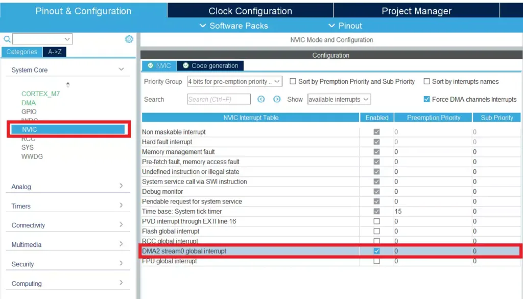
Now we will enable the interrupt which will indicate to us if the transfer is done or any error during the process. Click NVIC and then select the DMA2 stream0 global Interrupt. Refer to the below image.
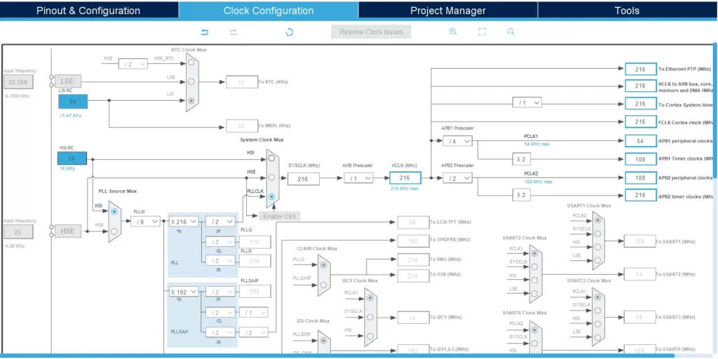
Now Configure the clock like below image.
|
|
|
Save the .ioc file and generate the code.
Source Code
[You can get the complete project source code on GitHub]
In this example, we are going to create two buffers and transfer the data from one to another with the help of DMA. We enabled the interrupt for DMA. So, when it completes the transfer it will call our callback function. Let’s define the callback and data buffers.
Note: Whenever you are adding your code, you must include your code between the USER CODE BEGIN and USER CODE END. If you add your code anywhere else, then it will be removed when you regenerate the code. Keep this in your mind.
/* USER CODE BEGIN 0 */
void DmaXferCompleteCallback(DMA_HandleTypeDef *hdma);				// Data Transfer Complete callback
static char Source[]={'E', 'm', 'b', 'e', 'T', 'r', 'o', 'n', 'i', 'c', 'X'};
static char Dest[20];
/* USER CODE END 0 */
Create the function definition for DmaXferCompleteCallback.
|
|
|
/* USER CODE BEGIN 4 */
void DmaXferCompleteCallback(DMA_HandleTypeDef *hdma)
{
	//Code will reach here if the Transfer completes
	__NOP();
}
/* USER CODE END 4 */
Now, we will configure the callback and start the DMA in the main function.
/* USER CODE BEGIN 2 */
  hdma_memtomem_dma2_stream0.XferCpltCallback = &DmaXferCompleteCallback;
  HAL_DMA_Start_IT(&hdma_memtomem_dma2_stream0,(uint32_t)Source,(uint32_t)Dest,sizeof(Source));
  /* USER CODE END 2 */
There are other callback functions that we can register if we want. If we want to see the error then we need to create one more callback function and register it with the XferErrorCallback parameter. Likewise, we can use the callback functions below.
XferAbortCallback– DMA transfer Abort callbackXferHalfCpltCallback– DMA Half transfer complete callback
Full Source Code
/* USER CODE BEGIN Header */
/**
  ******************************************************************************
  * @file           : main.c
  * @brief          : Main program body
  ******************************************************************************
  * @attention
  *
  * Copyright (c) 2023 STMicroelectronics.
  * All rights reserved.
  *
  * This software is licensed under terms that can be found in the LICENSE file
  * in the root directory of this software component.
  * If no LICENSE file comes with this software, it is provided AS-IS.
  *
  ******************************************************************************
  */
/* USER CODE END Header */
/* Includes ------------------------------------------------------------------*/
#include "main.h"

/* Private includes ----------------------------------------------------------*/
/* USER CODE BEGIN Includes */

/* USER CODE END Includes */

/* Private typedef -----------------------------------------------------------*/
/* USER CODE BEGIN PTD */

/* USER CODE END PTD */

/* Private define ------------------------------------------------------------*/
/* USER CODE BEGIN PD */

/* USER CODE END PD */

/* Private macro -------------------------------------------------------------*/
/* USER CODE BEGIN PM */

/* USER CODE END PM */

/* Private variables ---------------------------------------------------------*/

DMA_HandleTypeDef hdma_memtomem_dma2_stream0;
/* USER CODE BEGIN PV */

/* USER CODE END PV */

/* Private function prototypes -----------------------------------------------*/
void SystemClock_Config(void);
static void MPU_Config(void);
static void MX_DMA_Init(void);
/* USER CODE BEGIN PFP */

/* USER CODE END PFP */

/* Private user code ---------------------------------------------------------*/
/* USER CODE BEGIN 0 */
void DmaXferCompleteCallback(DMA_HandleTypeDef *hdma);				// Data Transfer Complete callback
static char Source[]={'E', 'm', 'b', 'e', 'T', 'r', 'o', 'n', 'i', 'c', 'X'};
static char Dest[20];
/* USER CODE END 0 */

/**
  * @brief  The application entry point.
  * @retval int
  */
int main(void)
{
  /* USER CODE BEGIN 1 */

  /* USER CODE END 1 */

  /* MPU Configuration--------------------------------------------------------*/
  MPU_Config();

  /* MCU Configuration--------------------------------------------------------*/

  /* Reset of all peripherals, Initializes the Flash interface and the Systick. */
  HAL_Init();

  /* USER CODE BEGIN Init */

  /* USER CODE END Init */

  /* Configure the system clock */
  SystemClock_Config();

  /* USER CODE BEGIN SysInit */

  /* USER CODE END SysInit */

  /* Initialize all configured peripherals */
  MX_DMA_Init();
  /* USER CODE BEGIN 2 */
  hdma_memtomem_dma2_stream0.XferCpltCallback = &DmaXferCompleteCallback;
  HAL_DMA_Start_IT(&hdma_memtomem_dma2_stream0,(uint32_t)Source,(uint32_t)Dest,sizeof(Source));
  /* USER CODE END 2 */

  /* Infinite loop */
  /* USER CODE BEGIN WHILE */
  while (1)
  {
    /* USER CODE END WHILE */

    /* USER CODE BEGIN 3 */
  }
  /* USER CODE END 3 */
}

/**
  * @brief System Clock Configuration
  * @retval None
  */
void SystemClock_Config(void)
{
  RCC_OscInitTypeDef RCC_OscInitStruct = {0};
  RCC_ClkInitTypeDef RCC_ClkInitStruct = {0};

  /** Configure the main internal regulator output voltage
  */
  __HAL_RCC_PWR_CLK_ENABLE();
  __HAL_PWR_VOLTAGESCALING_CONFIG(PWR_REGULATOR_VOLTAGE_SCALE1);

  /** Initializes the RCC Oscillators according to the specified parameters
  * in the RCC_OscInitTypeDef structure.
  */
  RCC_OscInitStruct.OscillatorType = RCC_OSCILLATORTYPE_HSI;
  RCC_OscInitStruct.HSIState = RCC_HSI_ON;
  RCC_OscInitStruct.HSICalibrationValue = RCC_HSICALIBRATION_DEFAULT;
  RCC_OscInitStruct.PLL.PLLState = RCC_PLL_ON;
  RCC_OscInitStruct.PLL.PLLSource = RCC_PLLSOURCE_HSI;
  RCC_OscInitStruct.PLL.PLLM = 8;
  RCC_OscInitStruct.PLL.PLLN = 216;
  RCC_OscInitStruct.PLL.PLLP = RCC_PLLP_DIV2;
  RCC_OscInitStruct.PLL.PLLQ = 2;
  RCC_OscInitStruct.PLL.PLLR = 2;
  if (HAL_RCC_OscConfig(&RCC_OscInitStruct) != HAL_OK)
  {
    Error_Handler();
  }

  /** Activate the Over-Drive mode
  */
  if (HAL_PWREx_EnableOverDrive() != HAL_OK)
  {
    Error_Handler();
  }

  /** Initializes the CPU, AHB and APB buses clocks
  */
  RCC_ClkInitStruct.ClockType = RCC_CLOCKTYPE_HCLK|RCC_CLOCKTYPE_SYSCLK
                              |RCC_CLOCKTYPE_PCLK1|RCC_CLOCKTYPE_PCLK2;
  RCC_ClkInitStruct.SYSCLKSource = RCC_SYSCLKSOURCE_PLLCLK;
  RCC_ClkInitStruct.AHBCLKDivider = RCC_SYSCLK_DIV1;
  RCC_ClkInitStruct.APB1CLKDivider = RCC_HCLK_DIV4;
  RCC_ClkInitStruct.APB2CLKDivider = RCC_HCLK_DIV2;

  if (HAL_RCC_ClockConfig(&RCC_ClkInitStruct, FLASH_LATENCY_7) != HAL_OK)
  {
    Error_Handler();
  }
}

/**
  * Enable DMA controller clock
  * Configure DMA for memory to memory transfers
  *   hdma_memtomem_dma2_stream0
  */
static void MX_DMA_Init(void)
{

  /* DMA controller clock enable */
  __HAL_RCC_DMA2_CLK_ENABLE();

  /* Configure DMA request hdma_memtomem_dma2_stream0 on DMA2_Stream0 */
  hdma_memtomem_dma2_stream0.Instance = DMA2_Stream0;
  hdma_memtomem_dma2_stream0.Init.Channel = DMA_CHANNEL_0;
  hdma_memtomem_dma2_stream0.Init.Direction = DMA_MEMORY_TO_MEMORY;
  hdma_memtomem_dma2_stream0.Init.PeriphInc = DMA_PINC_ENABLE;
  hdma_memtomem_dma2_stream0.Init.MemInc = DMA_MINC_ENABLE;
  hdma_memtomem_dma2_stream0.Init.PeriphDataAlignment = DMA_PDATAALIGN_BYTE;
  hdma_memtomem_dma2_stream0.Init.MemDataAlignment = DMA_MDATAALIGN_BYTE;
  hdma_memtomem_dma2_stream0.Init.Mode = DMA_NORMAL;
  hdma_memtomem_dma2_stream0.Init.Priority = DMA_PRIORITY_LOW;
  hdma_memtomem_dma2_stream0.Init.FIFOMode = DMA_FIFOMODE_ENABLE;
  hdma_memtomem_dma2_stream0.Init.FIFOThreshold = DMA_FIFO_THRESHOLD_FULL;
  hdma_memtomem_dma2_stream0.Init.MemBurst = DMA_MBURST_SINGLE;
  hdma_memtomem_dma2_stream0.Init.PeriphBurst = DMA_PBURST_SINGLE;
  if (HAL_DMA_Init(&hdma_memtomem_dma2_stream0) != HAL_OK)
  {
    Error_Handler( );
  }

  /* DMA interrupt init */
  /* DMA2_Stream0_IRQn interrupt configuration */
  HAL_NVIC_SetPriority(DMA2_Stream0_IRQn, 0, 0);
  HAL_NVIC_EnableIRQ(DMA2_Stream0_IRQn);

}

/* USER CODE BEGIN 4 */
void DmaXferCompleteCallback(DMA_HandleTypeDef *hdma)
{
	//Code will reach here if the Transfer completes
	__NOP();
}
/* USER CODE END 4 */

/* MPU Configuration */

void MPU_Config(void)
{
  MPU_Region_InitTypeDef MPU_InitStruct = {0};

  /* Disables the MPU */
  HAL_MPU_Disable();

  /** Initializes and configures the Region and the memory to be protected
  */
  MPU_InitStruct.Enable = MPU_REGION_ENABLE;
  MPU_InitStruct.Number = MPU_REGION_NUMBER0;
  MPU_InitStruct.BaseAddress = 0x0;
  MPU_InitStruct.Size = MPU_REGION_SIZE_4GB;
  MPU_InitStruct.SubRegionDisable = 0x87;
  MPU_InitStruct.TypeExtField = MPU_TEX_LEVEL0;
  MPU_InitStruct.AccessPermission = MPU_REGION_NO_ACCESS;
  MPU_InitStruct.DisableExec = MPU_INSTRUCTION_ACCESS_DISABLE;
  MPU_InitStruct.IsShareable = MPU_ACCESS_SHAREABLE;
  MPU_InitStruct.IsCacheable = MPU_ACCESS_NOT_CACHEABLE;
  MPU_InitStruct.IsBufferable = MPU_ACCESS_NOT_BUFFERABLE;

  HAL_MPU_ConfigRegion(&MPU_InitStruct);
  /* Enables the MPU */
  HAL_MPU_Enable(MPU_PRIVILEGED_DEFAULT);

}

/**
  * @brief  This function is executed in case of error occurrence.
  * @retval None
  */
void Error_Handler(void)
{
  /* USER CODE BEGIN Error_Handler_Debug */
  /* User can add his own implementation to report the HAL error return state */
  __disable_irq();
  while (1)
  {
  }
  /* USER CODE END Error_Handler_Debug */
}

#ifdef  USE_FULL_ASSERT
/**
  * @brief  Reports the name of the source file and the source line number
  *         where the assert_param error has occurred.
  * @param  file: pointer to the source file name
  * @param  line: assert_param error line source number
  * @retval None
  */
void assert_failed(uint8_t *file, uint32_t line)
{
  /* USER CODE BEGIN 6 */
  /* User can add his own implementation to report the file name and line number,
     ex: printf("Wrong parameters value: file %s on line %d\r\n", file, line) */
  /* USER CODE END 6 */
}
#endif /* USE_FULL_ASSERT */
Demo
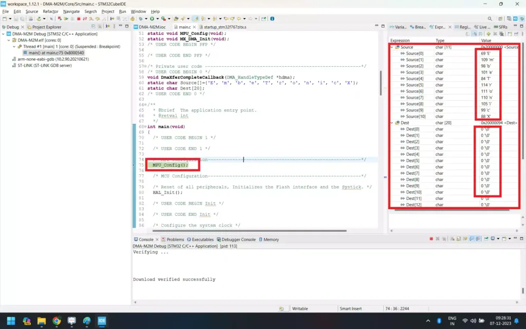
The code is ready. Now add the break-point in DmaXferCompleteCallback function. Click Debug to run step-by-step ![]() . Now see the
. Now see the Dest Buffer. It is empty. Check the below image.
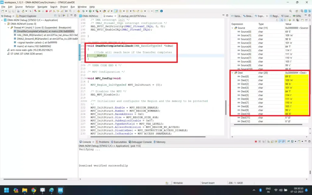
Then Click Resume to continue the execution ![]() . The breakpoint will hit once the transfer is completed. Check the
. The breakpoint will hit once the transfer is completed. Check the Dest buffer. The content of the Source buffer is copied to the Dest buffer. Check the below image.
See, the data has been transferred to the Dest buffer from the Source buffer. In our next article, we will see how to transfer the data from peripheral (UART) to memory and Memory to Peripheral (UART) using the STM32 DMA.
|
|
|
You can also read the below tutorials.
Reference:
- https://www.st.com/resource/en/programming_manual/pm0253-stm32f7-series-and-stm32h7-series-cortexm7-processor-programming-manual-stmicroelectronics.pdf
- https://www.st.com/resource/en/reference_manual/rm0410-stm32f76xxx-and-stm32f77xxx-advanced-armbased-32bit-mcus-stmicroelectronics.pdf
- https://www.st.com/resource/en/application_note/an4031-using-the-stm32f2-stm32f4-and-stm32f7-series-dma-controller-stmicroelectronics.pdf

Embedded Software | Firmware | Linux Devic Deriver | RTOS
Hi, I am a tech blogger and an Embedded Engineer. I am always eager to learn and explore tech-related concepts. And also, I wanted to share my knowledge with everyone in a more straightforward way with easy practical examples. I strongly believe that learning by doing is more powerful than just learning by reading. I love to do experiments. If you want to help or support me on my journey, consider sharing my articles, or Buy me a Coffee! Thank you for reading my blog! Happy learning!

