This is the Series of tutorials on the STM32 Microcontroller. The aim of this series is to provide easy and practical examples that anyone can understand. In our last article, we have seen STM32 USB Host Example. In this tutorial, we are going to see how to use the STM32 as a USB stick using the RAM Memory – STM32 USB Device MSC Tutorial.
Table of Contents
Hardware Required
- STM32F767Zi Nucleo Board
- Micro USB Cable (which supports data transfer)
STM32 USB Device MSC using RAM Memory
In our previous article, we made the STM32 as a USB host. So, when we connect other USB Devices like Pendrive or USB Stick to the STM32, we can access the files available in the USB device or even create the files.
In this article, we are going to make the STM32 as a USB device. A USB device is a peripheral that can be connected to a USB host via a USB cable. In this example, the computer is going to act as a USB host.
STM32F767Zi has USB OTG Full Speed and USB OTG High-Speed capability (with the ULPI). The USB OTG is a dual-role device (DRD) controller that supports both device and host functions and is fully compliant with the On-The-Go Supplement to the USB 2.0 Specification. It can also be configured as a host-only or device-only controller, fully compliant with the USB 2.0 Specification.
In this article, we are going to see STM32 USB Device MSC (Device-Only mode).
|
|
|
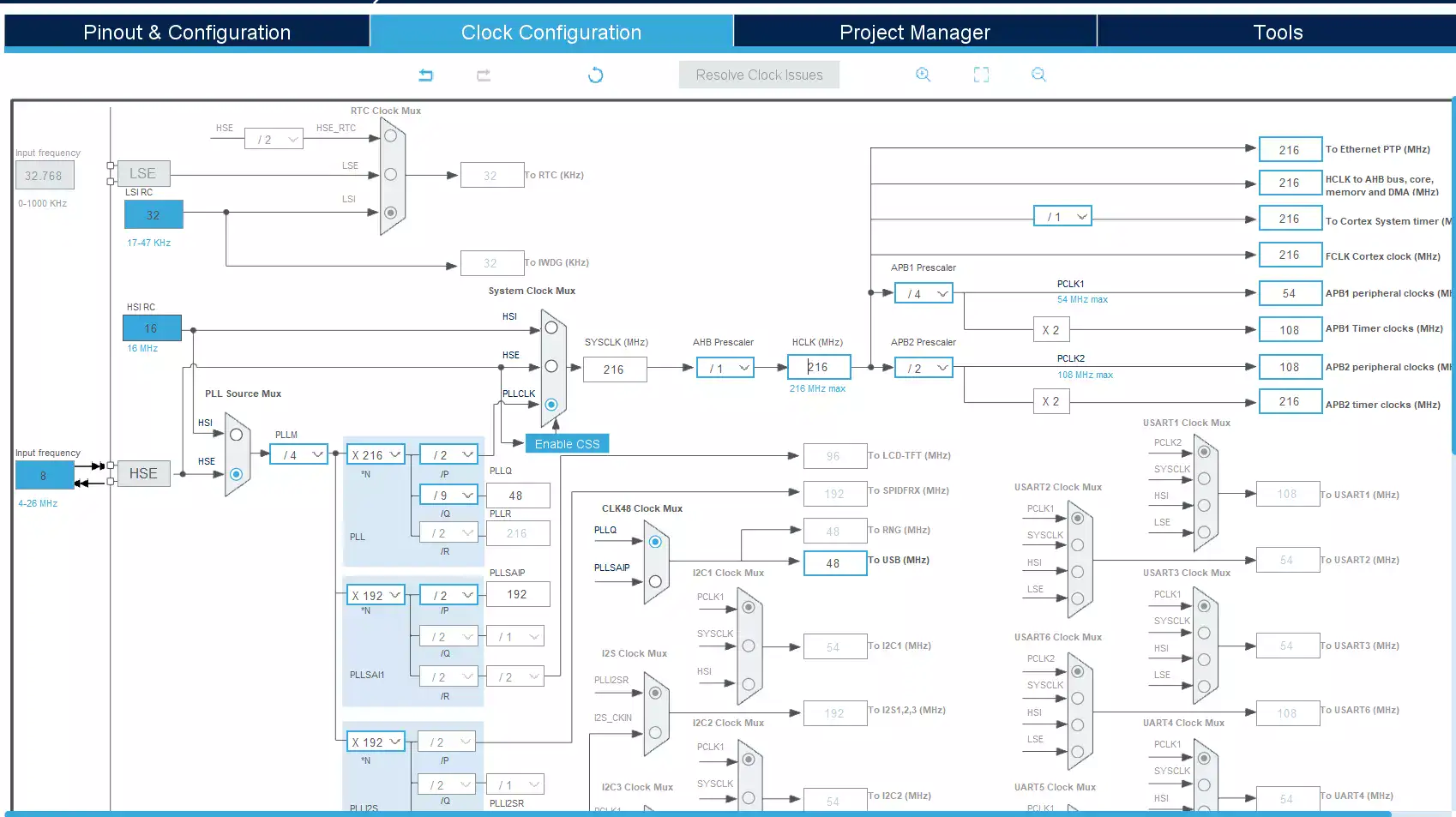
We need to give the 48MHz clock to the USB OTG from RCC. The STM32 Nucleo-144 board supports USB OTG or device-full-speed communication via a USB Micro-AB connector (CN13) and USB power switch (U12) connected to VBUS.
STM32 USB Device Example
Project Creation
Create the new STM32 project in STM32CubeIDE.
Note: This project was set up with STM32CubeMx V6.10 using STM32Cube FW_F7 V1.17.1.
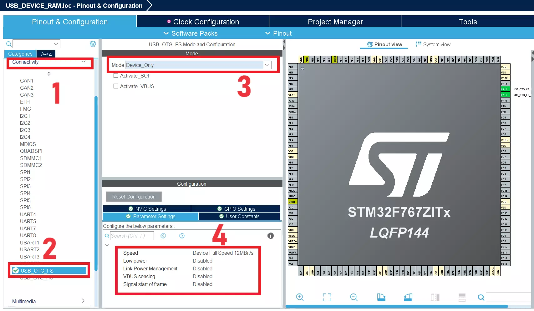
Configure USB OTG
Click “Connectivity” –> USB_OTG_FS, then set the Mode as Device_Only. Refer to the below image.
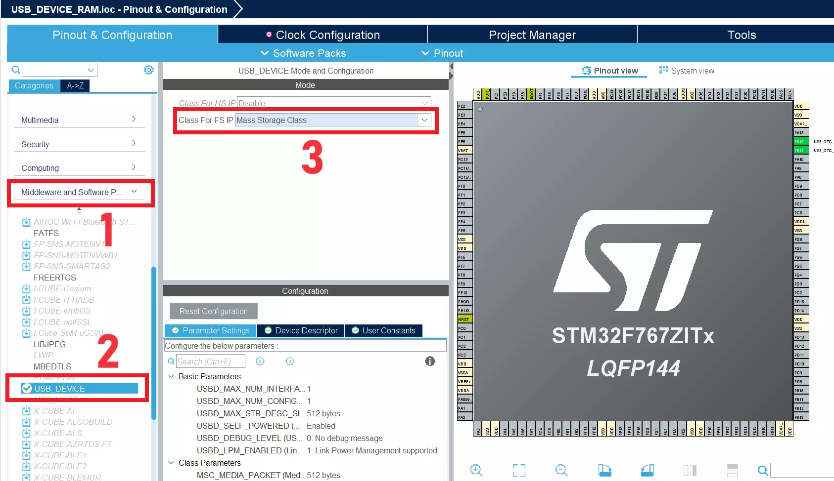
Configure USB Device
Now, click Middleware and Software –> USB_DEVICE. Then set the Class forFS IP to Mass Storage Host Class. Please refer to the below image.
|
|
|
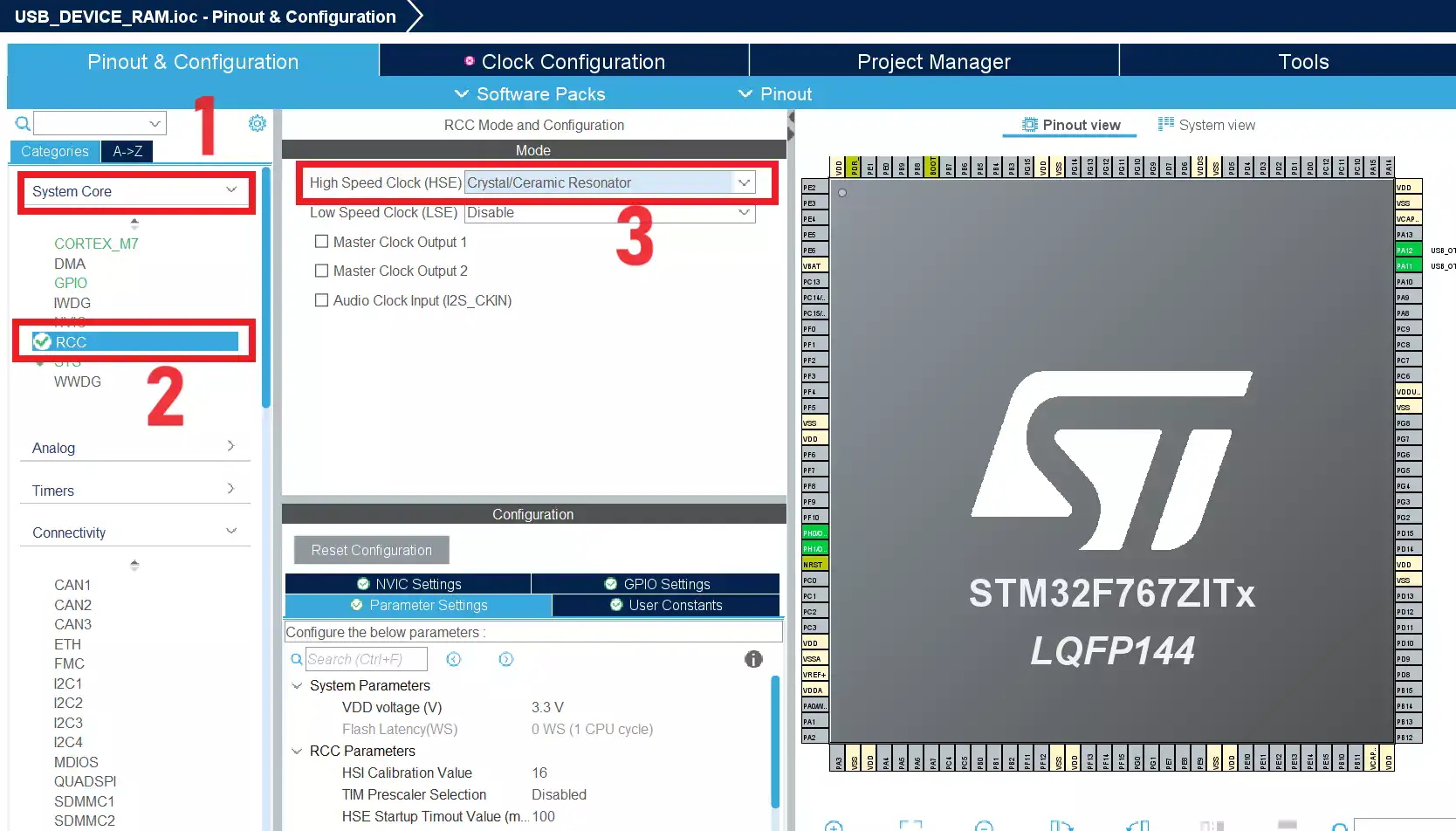
Configure Clock
We need to give the 48MHz to the USB. We are going to use our HSE clock which gets 8MHz. Click RCC and Set the HSE to Crystal/Ceramic Resonator like the below image.
Then configure the clock like below.
Save the .ioc file and generate the code.
Source Code – STM32 USB Device MSC Example
In this example, we are going to use the RAM memory for this STM32 USB Device example.
STM32F767Zi has 512KB RAM. In that, we are going to use 200Kb bytes of data for this purpose.
|
|
|
[You can get the complete project source code on GitHub]
Open the USB_DEVICE–>App–>usbd_storage_if.c file. In that file, we have to provide the allocated memory size. We decided to use 200KB bytes. In that code, block size (STORAGE_BLK_SIZ) is defined as 0x200 (512 bytes). So in order to use 200Kb, we need to assign 400 blocks (400 x 0x200 = 200KB). So, set STORAGE_BLK_NBR as 400. Refer to the code below.
#define STORAGE_LUN_NBR                  1
#define STORAGE_BLK_NBR                  400
#define STORAGE_BLK_SIZ                  0x200
Now we will create our buffer of 200Kb. Since we are going to use the RAM for this buffer, the content will be a garbage value in every reset. Because it will allocate in different areas in each reset. So, to avoid that, we will always allocate this buffer in the same location. To do that, we need to make modifications in the linker script and use the attribute keyword.
First, we will define the buffer. Add the below code between USER CODE BEGIN PRIVATE_VARIABLES and USER CODE END PRIVATE_VARIABLES.
/* USER CODE BEGIN PRIVATE_VARIABLES */
__attribute__ ((section (".usb_data"))) volatile uint8_t etx_buffer[STORAGE_BLK_NBR*STORAGE_BLK_SIZ];
/* USER CODE END PRIVATE_VARIABLES */
In the above code, we have created a buffer called etx_buffer in RAM, and we are telling the compiler to keep this buffer in a separate section called .usb_data using this command __attribute ((section (".usb_data"))).
|
|
|
Now, we will create this .usb_data section in the linker script. Add the below code to the STM32F767ZITX_FLASH.ld.
/* Keep USB Data Buffer. */
  .usb_data :
  {
  	KEEP(*(.keep.usb_data));
  } >RAM
You can get the complete linker script on GitHub.
Now go back to usbd_storage_if.c. We have created the buffer. Let’s add the read and write operation to that buffer.
Add the memcpy to the STORAGE_Read_FS() and STORAGE_Write_FS() function. Refer to the below code.
/**
  * @brief  Reads data from the medium.
  * @param  lun: Logical unit number.
  * @param  buf: data buffer.
  * @param  blk_addr: Logical block address.
  * @param  blk_len: Blocks number.
  * @retval USBD_OK if all operations are OK else USBD_FAIL
  */
int8_t STORAGE_Read_FS(uint8_t lun, uint8_t *buf, uint32_t blk_addr, uint16_t blk_len)
{
  /* USER CODE BEGIN 6 */

  memcpy(buf, (void*)&etx_buffer[blk_addr*STORAGE_BLK_SIZ], blk_len*STORAGE_BLK_SIZ);

  return (USBD_OK);
  /* USER CODE END 6 */
}

/**
  * @brief  Writes data into the medium.
  * @param  lun: Logical unit number.
  * @param  buf: data buffer.
  * @param  blk_addr: Logical block address.
  * @param  blk_len: Blocks number.
  * @retval USBD_OK if all operations are OK else USBD_FAIL
  */
int8_t STORAGE_Write_FS(uint8_t lun, uint8_t *buf, uint32_t blk_addr, uint16_t blk_len)
{
  /* USER CODE BEGIN 7 */

  memcpy((void*)&etx_buffer[blk_addr*STORAGE_BLK_SIZ], buf, blk_len*STORAGE_BLK_SIZ);

  return (USBD_OK);
  /* USER CODE END 7 */
}
STORAGE_Read_FS() function will be called when we read the USB device. So, we need to copy the data from the etx_buffer to the function’s buf.
|
|
|
STORAGE_Write_FS() function will be called when we write the data to the USB device. So, in that function, we need to transfer the data to the etx_buffer from function’s buf.
You can get the complete project from the GitHub.
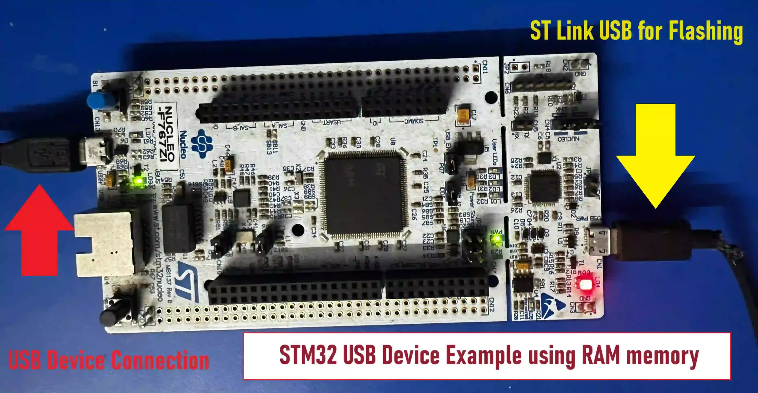
Hardware Connection – STM32 USB Device
There are two USB ports available in this STM32F767Zi Nucleo Board. One is for ST-Link, and the other is for our USB communication. CN13 USB port is ours. So connect both USB Ports to the Computer (One is to flash the code, the other one is for USB data transfer). Refer to the below image.
Demo – STM32 USB Device Example
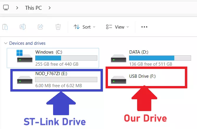
The code is ready. Build the code and flash it. You can see our USB drive. When you open it for the first time, it will ask you to format that USB drive. Format it and open that. You can create the file and do your file operations.
When you press the reset button or do a reset from the software (soft reset), the data will persist. Because we have created the data buffer in a separate area (.usb_data). But when we do a power-on reset, the data will be gone as the startup code initializes the RAM data to zero. If you want to overcome this problem, you need to make the changes in the startup_stm32f767xx.s file.
|
|
|
Please read the other STM32 Tutorials.
In our next article, we will see STM32 USB Device MSC using Flash Memory.
You can read the below tutorials.
Embedded Software | Firmware | Linux Devic Deriver | RTOS
Hi, I am a tech blogger and an Embedded Engineer. I am always eager to learn and explore tech-related concepts. And also, I wanted to share my knowledge with everyone in a more straightforward way with easy practical examples. I strongly believe that learning by doing is more powerful than just learning by reading. I love to do experiments. If you want to help or support me on my journey, consider sharing my articles, or Buy me a Coffee! Thank you for reading my blog! Happy learning!
