This is the Series of tutorials on the STM32 Microcontroller. The aim of this series is to provide easy and practical examples that anyone can understand. This is the STM32 SPI using Arduino IDE Tutorial. In this tutorial, we will learn how to use the SPI (Serial Peripheral Interface) communication protocol with STM32 microcontrollers using the Arduino framework.
Table of Contents
STM32 SPI using Arduino IDE Tutorial
What is the SPI Protocol?
SPI is a widely used interface in embedded systems for communication between microcontrollers and peripheral devices such as sensors, displays, and memory chips. We have detailly discussed this SPI protocol in our website. Please take a look.
Prerequisites
To follow along with this tutorial, you will need the following:
- Any STM32 microcontroller board (e.g., STM32F446ZE)
- An Arduino development environment
- USB cable for connecting the STM32 board to your computer
- Basic knowledge of Arduino programming
- Logic Analyzer to capture the SPI Data
Setting up the Hardware and Software
Before we start coding, let’s set up the hardware:
- Connect the STM32 board to your computer using the USB cable.
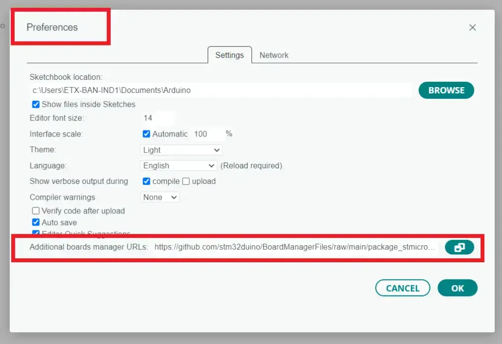
- We will have to install the STM32 Add-on in your Arduino IDE. Go to File > Preferences. Add the URL below to the Additional Board Manager URLs text box.
https://github.com/stm32duino/BoardManagerFiles/raw/main/package_stmicroelectronics_index.json
If the text box is not empty, you can separate the URLs with a comma. Check the below image for your reference.
|
|
|
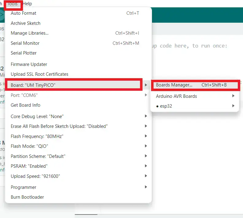
- Then go to “Tools” > “Board” > “Boards Manager“. Check the below image.
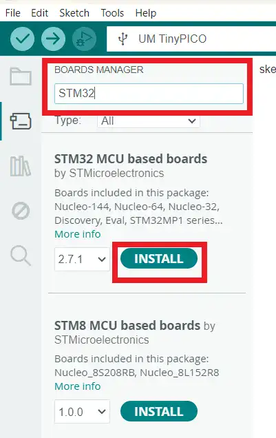
- Search for STM32, select the latest version, and click Install. Check the below image.
- There are a few megabytes of data to download and install, so be patient. Once the installation is completed, quit and restart the Arduino IDE.
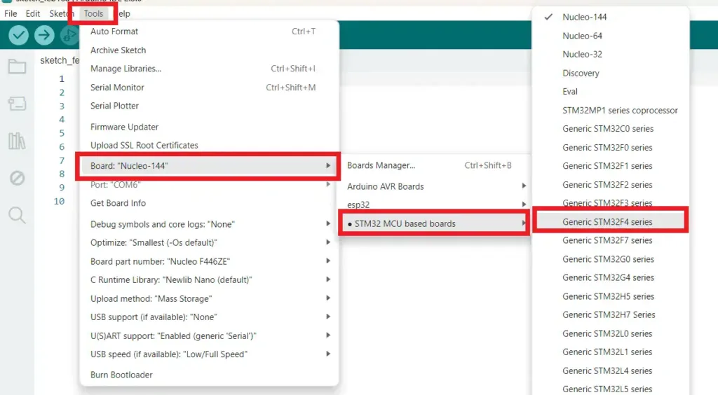
- Then go to “Tools” > “Board” and select your STM32 board from the list. Check the below image. In my case, we have selected Nucleo 144 and STM32F4 Series.
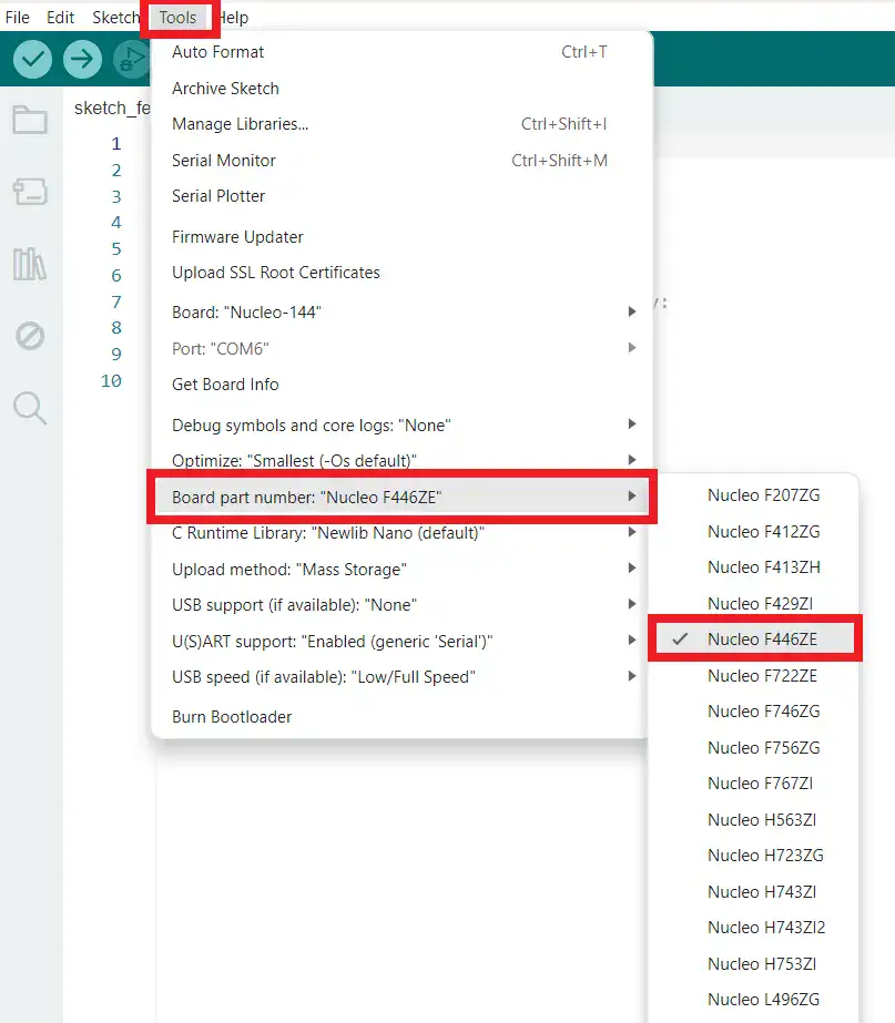
- Now Select the Board part number. Refer to the below image.
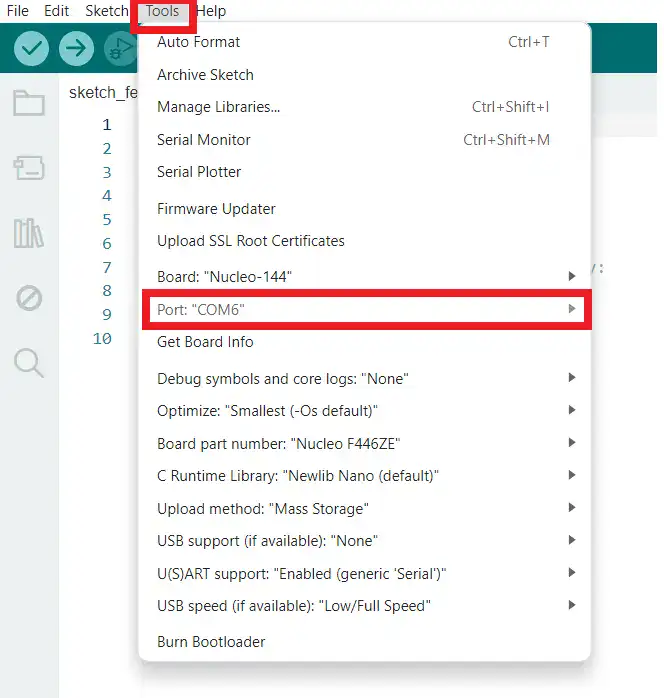
- Choose the appropriate COM port under “Tools” > “Port“. Refer to the below image.
Configuring the SPI Interface in the Arduino IDE
Now, let’s configure the SPI interface on the STM32 microcontroller.
Open a new Arduino sketch and include the necessary libraries.
#include <SPI.h>
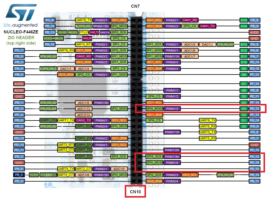
Define the SPI pins. In this example, we are going to use the PE12, PE13, PE14, PE15 (SPI4).
- MOSI – PE14
- MISO – PE13
- SCLK – PE12
- Slave Select – PE15
#define MOSI_PIN   PE14   //MOSI Pin
#define MISO_PIN   PE13   //MISO Pin
#define SCLK_PIN   PE12   //Clock Pin
#define CS_PIN     PE15   //Chip Select or Slave Select Pin
Now, we will initialize the SPI class like below.
SPIClass etx_spi( MOSI_PIN, MISO_PIN, SCLK_PIN );
By using the above code, we have created the etx_spi object. We can use that object in our code.
|
|
|
Let’s Initialize the SPI interface in the setup function.
etx_spi.begin();
We have to define the Slave select pin separately. Check the full source code for full understanding.
Now we will set the SPI settings. This step is optional.
etx_spi.beginTransaction(SPISettings(1000000, MSBFIRST, SPI_MODE0));
The above code sets the SPI clock frequency to 1 MHz, the most significant bit first, and the SPI mode to 0.
Using the SPI Interface
Now that we have configured the SPI interface, let’s use it to communicate with a peripheral device. In this example, we will send data from an SPI device.
|
|
|
- Select the SPI device by pulling its SS pin low.
- Send data (
0xA1) to the device using the SPI transfer function. - Deselect the SPI device by pulling its SS pin high.
//Chip Select Low
digitalWrite(CS_PIN, LOW);

//Transfer data
etx_spi.transfer(0xA1);

//Chip Select Low
digitalWrite(CS_PIN, HIGH);
Check the full source code below.
STM32 Arduino SPI Example – Full Source Code
#include <SPI.h>

#define MOSI_PIN   PE14   //MOSI Pin
#define MISO_PIN   PE13   //MISO Pin
#define SCLK_PIN   PE12   //Clock Pin
#define CS_PIN     PE15   //Chip Select or Slave Select Pin

SPIClass etx_spi( MOSI_PIN, MISO_PIN, SCLK_PIN );

void setup() {
  etx_spi.setSCLK(SCLK_PIN);
  etx_spi.setMOSI(MOSI_PIN);
  etx_spi.setMISO(MISO_PIN);

  etx_spi.begin();
  pinMode(CS_PIN, OUTPUT);
  digitalWrite(CS_PIN, HIGH);
}

void loop() {
  //Chip Select Low
  digitalWrite(CS_PIN, LOW);

  //Transfer data
  etx_spi.transfer(0xA1);

  //Chip Select Low
  digitalWrite(CS_PIN, HIGH);

  //delay
  delay(100);
}
STM32 Arduino SPI Example – Demo and Testing
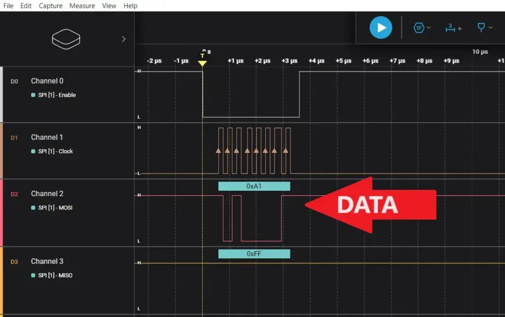
The code is ready. Flash the code. Connect the logic analyzer to those SPI pins. Reset the controller. See the data. 0xA1 is transmitted by the STM32 microcontroller. Check the below image.
Conclusion
In this tutorial, we have learned how to use the SPI interface with STM32 microcontrollers using the Arduino framework. We have covered the basic configuration and usage of the SPI interface and we have not used any slave device. In our next tutorial, we will connect the slave device (SD Card) and transfer the data.
Remember to consult the datasheets and documentation of the specific devices you are working with for detailed information on their SPI interface requirements and protocols.
You can also read the below tutorials.
|
|
|

Embedded Software | Firmware | Linux Devic Deriver | RTOS
Hi, I am a tech blogger and an Embedded Engineer. I am always eager to learn and explore tech-related concepts. And also, I wanted to share my knowledge with everyone in a more straightforward way with easy practical examples. I strongly believe that learning by doing is more powerful than just learning by reading. I love to do experiments. If you want to help or support me on my journey, consider sharing my articles, or Buy me a Coffee! Thank you for reading my blog! Happy learning!

