This article is a continuation of the Series on STM32F103 Bootloader and carries the discussion on Bootloader design and implementation. The aim of this series is to provide easy and practical examples that anyone can understand. In our last post, we developed the bootloader which calls the application. In this post, we will implement STM32F1 Firmware Update using Custom Bootloader – Bootloader Development Tutorial Part 3
We have attached the video explanation also at the bottom of this post. If you are using STM32F7 (ARM Cortex M7), then you can check these tutorials.
Table of Contents
Prerequisites
In this simple STM32F103 bootloader example, we will be using the concepts which have been explained already in the below-given tutorials. So I would request you to go through those tutorials first if you are not familiar with those topics.
We are providing the video format of this Bootloader series. Please check out the video playlist. You can also get the source code of this tutorial from GitHub.
Hardware and Tools Required
We have our own EmbeTronicX Store called ChipTronicX. You can purchase the hardware from ChipTronicX.
|
|
|
- STM32F103 Blue Pill board (You can use any STM32 boards. But use the addresses based on your controller).
- LED (If you don’t have onboard LED)
- STM32Cube IDE
- STLink Utility or STM32Cube Programmer
- USB to Serial Converter
Firmware Update using Custom Bootloader
Custom Bootloader in STM32F103
Before designing the bootloader, If you know what happens when you press the reset button in the microcontroller, that will be helpful for you to understand better.
Designing our custom bootloader
As per our previous post, we will have to keep the bootloader at 0x08000000 and the application at 0x08004400.
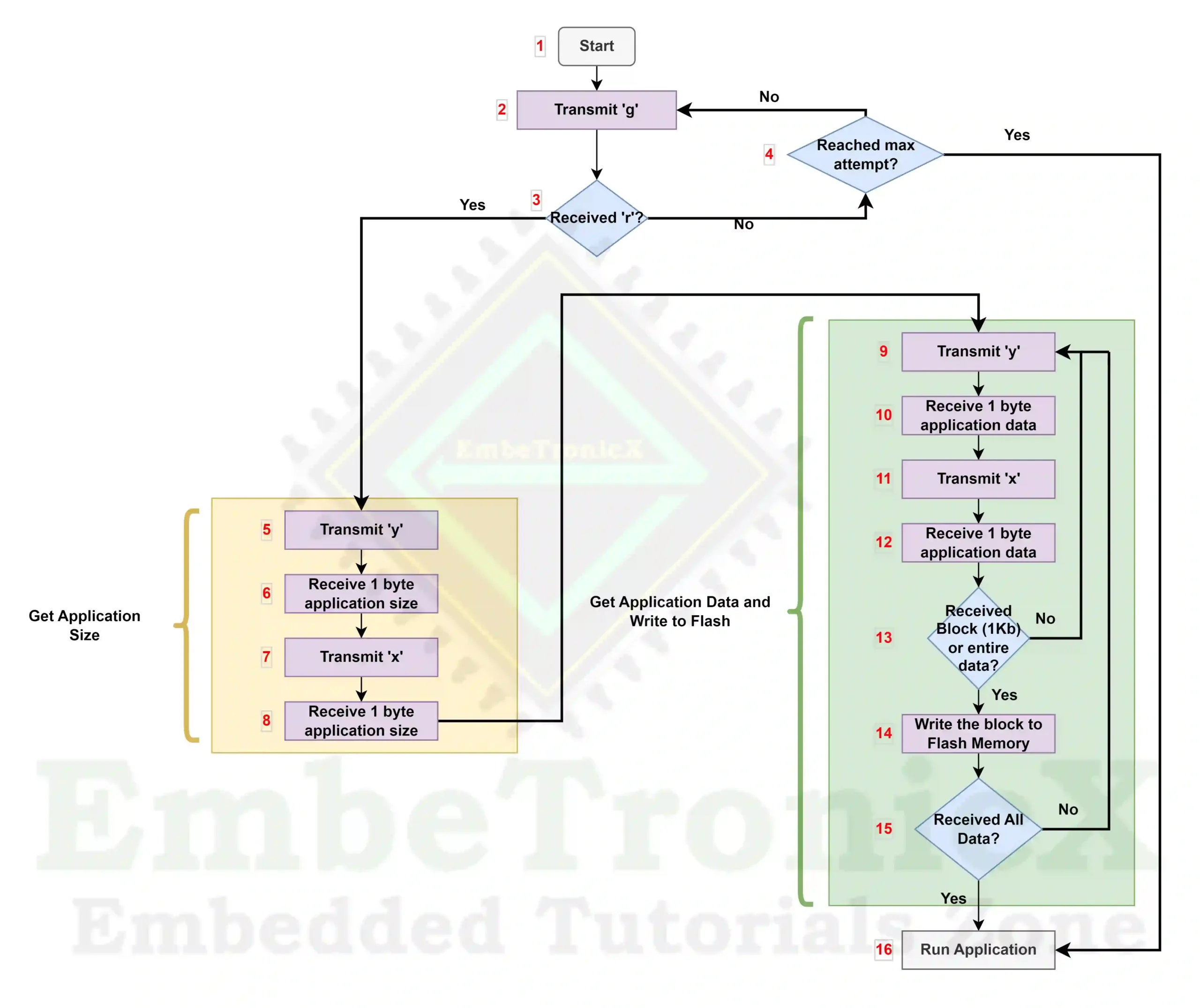
Now we will design the bootloader. Please check the design and flow chart of the STM32F103 bootloader.
Note: This design is just for educational purposes. There may be something that we can improve. Some bugs also will be there in this design.
The bootloader process flow steps description is the following.
|
|
|
Block 1
The bootloader starts when the microcontroller power-up or resets.
- Goto Block 2.
Block 2
Transmit the character “g” through the USART to the host. In this example, we have used USART 3 for this data transfer.
- Goto Block 3.
Block 3
Check that we have received the character “r” from the host.
Block 4
Check that we have reached the maximum attempt. In this example, we set that count as 100.
- If it reached the maximum attempt, then go to Block 16.
- If it is not reached the maximum attempt, then go to Block 2.
Block 5
Till now we have got a response from the Host. Now we will receive the application size from the host. Now transmit the character ‘y’ to the host. Then go to Block 6.
|
|
|
Block 6
Receive the 1-byte data from the host. Then go to Block 7.
Block 7
Now transmit the character “x” to the host. Then go to Block 8.
Block 8
Receive the 1-byte data from the host. Now we can combine the bytes that we have received from Block 6 and Block 8 to get the application size. Then go to Block 9.
Block 9
Now we can receive the application data from the host. Transmit the character ‘y’ to the host. Then go to Block 10.
Block 10
Receive the 1-byte data from the host. Then go to Block 11.
|
|
|
Block 11
Now transmit the character “x” to the host. Then go to Block 8.
Block 12
Receive the 1-byte data from the host. Go to Block 13.
Block 13
Check that you have received all the data or the entire block of the data. In this example, we have set the block size as 1024 bytes.
Block 14
Write the data into the flash memory. Then go to Block 15.
Block 15
Check that you have received the entire application data.
|
|
|
Block 16
Now we have received the full data and written it into the flash memory or we did not receive any data from the host. Now, we can run our new or old application. Call the application reset handler using the function pointer.
That’s it. Now we will implement the above concept in the code.
Connection Diagram
- LED – Onboard LED (PC13)
- USART1 (PA9 and PA10) – For debug prints
- USART3 (PB10 and PB11) – For data transfer
STM32F1 Firmware Update using Custom Bootloader – Source code
Bootloader Code
I have added the below changes on top of the previous tutorial’s bootloader source code.
/* USER CODE BEGIN 4 */

#ifdef __GNUC__
  /* With GCC, small printf (option LD Linker->Libraries->Small printf
     set to 'Yes') calls __io_putchar() */
int __io_putchar(int ch)
#else
int fputc(int ch, FILE *f)
#endif /* __GNUC__ */
{
  /* Place your implementation of fputc here */
  /* e.g. write a character to the UART3 and Loop until the end of transmission */
  HAL_UART_Transmit(&huart1, (uint8_t *)&ch, 1, HAL_MAX_DELAY);

  return ch;
}


static int UART_Write_Loop( void )
{
  char tx = 'g';
  char rx = '0';
  HAL_StatusTypeDef ex;
  int ret = 0;
  int count = 0;

  while(1)
  {
    //Toggle GPIO
    HAL_GPIO_TogglePin(GPIOC, GPIO_PIN_13);

    HAL_UART_Transmit(&huart3, (uint8_t *)&tx, 1, HAL_MAX_DELAY);

    ex = HAL_UART_Receive(&huart3, (uint8_t *)&rx, 1, 10);

    if( ( ex == HAL_OK ) && ( rx == 'r' ) )
    {
      //received data
      printf("Firmware Update Started\r\n");
      ret = 1;
      break;
    }

    if( count == 100 )
    {
      //received nothing
      printf("No Data Received for Firmware Update\r\n");
      break;
    }
    count++;
    HAL_Delay(20);              //20ms delay
  }

  return ret;
}

/**
  * @brief Write data to the Application's actual flash location.
  * @param data data to be written
  * @param data_len data length
  * @is_first_block true - if this is first block, false - not first block
  * @retval HAL_StatusTypeDef
  */
static HAL_StatusTypeDef write_data_to_flash_app( uint8_t *data,
                                        uint16_t data_len, bool is_first_block )
{
  HAL_StatusTypeDef ret;

  do
  {
    ret = HAL_FLASH_Unlock();
    if( ret != HAL_OK )
    {
      break;
    }

    //No need to erase every time. Erase only the first time.
    if( is_first_block )
    {
      printf("Erasing the Flash memory...\r\n");
      //Erase the Flash
      FLASH_EraseInitTypeDef EraseInitStruct;
      uint32_t SectorError;

      EraseInitStruct.TypeErase     = FLASH_TYPEERASE_PAGES;
      EraseInitStruct.PageAddress   = ETX_APP_START_ADDRESS;
      EraseInitStruct.NbPages       = 47;                     //47 Pages

      ret = HAL_FLASHEx_Erase( &EraseInitStruct, &SectorError );
      if( ret != HAL_OK )
      {
        break;
      }
      application_write_idx = 0;
    }

    for(int i = 0; i < data_len/2; i++)
    {
      uint16_t halfword_data = data[i * 2] | (data[i * 2 + 1] << 8);
      ret = HAL_FLASH_Program( FLASH_TYPEPROGRAM_HALFWORD,
                               (ETX_APP_START_ADDRESS + application_write_idx ),
                               halfword_data
                             );
      if( ret == HAL_OK )
      {
        //update the data count
        application_write_idx += 2;
      }
      else
      {
        printf("Flash Write Error...HALT!!!\r\n");
        break;
      }
    }

    if( ret != HAL_OK )
    {
      break;
    }

    ret = HAL_FLASH_Lock();
    if( ret != HAL_OK )
    {
      break;
    }
  }while( false );

  return ret;
}


/**
  * @brief Check for Firmware Update and update the Firmware
  * @retval None
  */
static void Firmware_Update(void)
{
  uint8_t xx,yy;
  uint8_t x = 'x';
  uint8_t y = 'y';
  HAL_StatusTypeDef ex = HAL_OK;
  uint16_t current_app_size = 0;
  uint16_t i = 0;

  uint8_t block[MAX_BLOCK_SIZE] = { 0 };

  do
  {
    if( UART_Write_Loop() != 0 )
    {
      //Sender is ready. Receive the Firmware Size

      // Ask yy
      HAL_UART_Transmit(&huart3, &y, 1, HAL_MAX_DELAY);
      ex = HAL_UART_Receive(&huart3, &yy, 1, 5000);
      if( ex != HAL_OK )
      {
        printf("Get application Size error (yy)...HALT!!!\r\n");
        break;
      }

      // Ask xx
      HAL_UART_Transmit(&huart3, &x, 1, HAL_MAX_DELAY);
      ex = HAL_UART_Receive(&huart3, &xx, 1, 5000);
      if( ex != HAL_OK )
      {
        printf("Get application Size error(XX)...HALT!!!\r\n");
        break;
      }

      application_size = yy | (xx << 8);
      printf("Application Size = %d bytes\r\n", application_size);

      while(1)
      {
        if( ( i == MAX_BLOCK_SIZE ) || ( current_app_size >= application_size) )
        {
          printf("Received Block[%d]\r\n", current_app_size/MAX_BLOCK_SIZE);

          //write to flash
          ex = write_data_to_flash_app(block, MAX_BLOCK_SIZE, (current_app_size <= MAX_BLOCK_SIZE) );

          if( ex != HAL_OK )
          {
            break;
          }

          //clear the memory
          memset(block, 0,MAX_BLOCK_SIZE);
          i = 0;
        }

        if( current_app_size >= application_size)
        {
          //received all data. exit
          ex = HAL_OK;
          break;
        }

        // Ask yy
        HAL_UART_Transmit(&huart3, &y, 1, HAL_MAX_DELAY);
        ex = HAL_UART_Receive(&huart3, &yy, 1, 5000);
        if( ex != HAL_OK )
        {
          printf("Get application data[index:%d] error (yy)...HALT!!!\r\n", i);
          break;
        }

        // Ask xx
        HAL_UART_Transmit(&huart3, &x, 1, HAL_MAX_DELAY);
        ex = HAL_UART_Receive(&huart3, &xx, 1, 5000);
        if( ex != HAL_OK )
        {
          printf("Get application data[index:%d] error(XX)...HALT!!!\r\n", i);
          break;
        }

        //--- Save xxyy in block[i]
        block[i++] = yy;
        block[i++] = xx;
        current_app_size += 2;
      }
    }
  }
  while( false );

  if( ex != HAL_OK )
  {
    while(1);
  }
}

static void goto_application( void )
{
	printf("Gonna Jump to Application...\n");
	void (*app_reset_handler)(void) = (void*)(*((volatile uint32_t*)(ETX_APP_START_ADDRESS + 4U)));

	if( app_reset_handler == (void*)0xFFFFFFFF )
	{
	  printf("Invalid Application... HALT!!!\r\n");
	  while(1);
	}

	__set_MSP(*(volatile uint32_t*) ETX_APP_START_ADDRESS);

	// Turn OFF the Led to tell the user that Bootloader is not running
  HAL_GPIO_WritePin(GPIOC, GPIO_PIN_13, GPIO_PIN_RESET );

	app_reset_handler();    //call the app reset handler
}

/* USER CODE END 4 */
The above code does that magic.
UART_Write_Loop() function writes the character “g” and receives the character “r” from the Host. If it receives “r”, then the host device will send the application data next. So, it will trigger the application update.
|
|
|
Firmware_Update() will receive the application data from the host device and write that data to the Flash memory using the write_data_to_flash_app() function.
goto_application() function starts the application.
You can get the entire bootloader source code of this project from GitHub.
Application Source Code
We have used the previous tutorial application image. You can get the application source code from GitHub.
Host Application Source Code
We have used the below source code for the PC application. You can get the PC Host application source code from GitHub.
|
|
|
/**************************************************
file: etx_ota_update_main.c
purpose:
compile with the command: gcc etx_ota_update_main.c RS232\rs232.c -IRS232 -Wall -Wextra -o2 -o etx_ota_app
**************************************************/
#include <stdint.h>
#include <stdlib.h>
#include <stdio.h>
#include <stdbool.h>

#ifdef _WIN32
#include <Windows.h>
#else
#include <unistd.h>
#endif

#include "rs232.h"

#define ETX_OTA_MAX_BLOCK_SIZE ( 1024 )
#define ETX_OTA_MAX_FW_SIZE    ( ETX_OTA_MAX_BLOCK_SIZE * 48 )

uint8_t APP_BIN[ETX_OTA_MAX_FW_SIZE];

void delay(uint32_t us)
{
#ifdef _WIN32
    //Sleep(ms);
    __int64 time1 = 0, time2 = 0, freq = 0;

    QueryPerformanceCounter((LARGE_INTEGER *) &time1);
    QueryPerformanceFrequency((LARGE_INTEGER *)&freq);

    do {
        QueryPerformanceCounter((LARGE_INTEGER *) &time2);
    } while((time2-time1) < us);
#else
    usleep(us);
#endif
}

int main(int argc, char *argv[])
{
  int comport;
  int bdrate   = 115200;       /* 115200 baud */
  char mode[]={'8','N','1',0}; /* *-bits, No parity, 1 stop bit */
  char bin_name[1024];
  int ex = 0;
  FILE *Fptr = NULL;

  do
  {
    if( argc <= 2 )
    {
      printf("Please feed the COM PORT number and the Application Image....!!!\n");
      printf("Example: .\\etx_ota_app.exe 8 ..\\..\\Application\\Debug\\Blinky.bin");
      ex = -1;
      break;
    }

    //get the COM port Number
    comport = atoi(argv[1]) -1;
    strcpy(bin_name, argv[2]);

    printf("Opening COM%d...\n", comport+1 );

    if( RS232_OpenComport(comport, bdrate, mode, 0) )
    {
      printf("Can not open comport\n");
      ex = -1;
      break;
    }

    printf("Opening Binary file : %s\n", bin_name);

    Fptr = fopen(bin_name,"rb");

    if( Fptr == NULL )
    {
      printf("Can not open %s\n", bin_name);
      ex = -1;
      break;
    }

    fseek(Fptr, 0L, SEEK_END);
    uint32_t app_size = ftell(Fptr);
    fseek(Fptr, 0L, SEEK_SET);

    printf("File size = %d\n", app_size);

    if( app_size > ETX_OTA_MAX_FW_SIZE )
    {
      printf("Application Size is more than the Maximum Size (%dKb)\n", ETX_OTA_MAX_FW_SIZE/ETX_OTA_MAX_BLOCK_SIZE);
      ex = -1;
      break;
    }

    //read the full image
    if( fread( APP_BIN, 1, app_size, Fptr ) != app_size )
    {
      printf("App/FW read Error\n");
      ex = -1;
      break;
    }

    unsigned char rec;

    printf("Waiting for OTA Start\n");
    do
    {
      RS232_PollComport( comport, &rec, 1);
    } while( rec != 'g' );

    printf("Sending r...\r\n");
    RS232_SendByte(comport, 'r');

    printf("Sending FW Size...\n");
    do
    {
      RS232_PollComport( comport, &rec, 1);
    } while( rec != 'y' );

    if( RS232_SendByte(comport, (uint8_t)app_size))
    {
      //some data missed.
      printf("OTA DATA : Send Err\n");
      ex = -1;
      break;
    }

    do
    {
      RS232_PollComport( comport, &rec, 1);
    } while( rec != 'x' );

    if( RS232_SendByte(comport, (uint8_t)(app_size >> 8)) )
    {
      //some data missed.
      printf("OTA DATA : Send Err\n");
      ex = -1;
      break;
    }

    printf("Sending Data...\n");

    for( uint32_t i = 0; i < app_size;)
    {
      do
      {
        RS232_PollComport( comport, &rec, 1);
      } while( rec != 'y' );

      if( RS232_SendByte(comport, APP_BIN[i++]) )
      {
        //some data missed.
        printf("OTA DATA : Send Err\n");
        ex = -1;
        break;
      }

      do
      {
        RS232_PollComport( comport, &rec, 1);
      } while( rec != 'x' );

      if( RS232_SendByte(comport, APP_BIN[i++]) )
      {
        //some data missed.
        printf("OTA DATA : Send Err\n");
        ex = -1;
        break;
      }
      if( ( i % ETX_OTA_MAX_BLOCK_SIZE ) == 0 )
      {
        printf("Block %d Transmitted...\r\n", i/ETX_OTA_MAX_BLOCK_SIZE);
      }

    }

    if( ex < 0 )
    {
      break;
    }

  } while (false);

  if(Fptr)
  {
    fclose(Fptr);
  }

  if( ex < 0 )
  {
    printf("OTA ERROR\n");
  }
  return(ex);
}
You can see the below video explanation for a better understanding.
STM32F1 Firmware Update using Custom Bootloader – Output
- Open the command prompt in the host application directory and build the host application using the below command.
gcc etx_ota_update_main.c RS232\rs232.c -IRS232 -Wall -Wextra -o2 -o etx_ota_app
- Then run the application with two arguments. (The first argument is COMPORT number, and the second argument is the Application binary path). See the example below.
.\etx_ota_app.exe 8 ..\..\Application\Debug\Application.bin
- Flash and run the bootloader at
0x08000000. - Now the OTA process starts. Wait until it finishes.
- Once it has flashed the application, then it automatically reboots.
- See the Serial terminal. You can see the application prints and also check the Onboard LED. Now it should blink with 1 seconds delay.
You can refer to the below video explanation. There we have given demo at the last.
Video Explanation
Please check our below video explanation.
|
|
|
You can also read the below tutorials.
Embedded Software | Firmware | Linux Devic Deriver | RTOS
Hi, I am a tech blogger and an Embedded Engineer. I am always eager to learn and explore tech-related concepts. And also, I wanted to share my knowledge with everyone in a more straightforward way with easy practical examples. I strongly believe that learning by doing is more powerful than just learning by reading. I love to do experiments. If you want to help or support me on my journey, consider sharing my articles, or Buy me a Coffee! Thank you for reading my blog! Happy learning!
