This article is a continuation of the Series on STM32 Bootloader and carries the discussion on Bootloader design and implementation. The aim of this series is to provide easy and practical examples that anyone can understand. This post is Simple STM32F103 Bootloader Implementation – Bootloader Tutorial Part 2.
We have attached the video explanation also at the bottom of this post. If you are using STM32F7 (ARM Cortex M7), then you can check these tutorials.
Table of Contents
Prerequisites
In this simple STM32F103 bootloader example, we will be using the concepts which have been explained already in the below-given tutorials. So I would request you to go through those tutorials first if you are not familiar with those topics.
We are providing the video format of this Bootloader series. Please check out the video playlist. You can also get the source code of this tutorial from GitHub.
Hardware Required
We have our own EmbeTronicX Store called ChipTronicX. You can purchase the hardware from ChipTronicX.
|
|
|
- STM32F103 Blue Pill board (You can use any STM32 boards. But use the addresses based on your controller).
- LED (If you don’t have onboard LED)
STM32F103 Features
This is STM32F103C8T6 Minimum System STM32 ARM Core Board. This board is a low-cost Minimum System Development Board for ARM Microcontroller STM32F103C8T6.
The board is suitable for learners that want to learn the STM32 microcontroller with ARM Cortex-M3 32-bit core.
- Arm® 32-bit Cortex®-M3 CPU core
- 72 MHz maximum frequency
- 64 or 128 Kbytes of Flash memory
- 20 Kbytes of SRAM
- 2x 12-bit, 1 µs A/D converters (up to 16 channels)
- Up to 80 fast I/O ports
- Seven timers
- Up to two I2C interfaces
- Up to three USARTs
- Up to two SPIs
- CAN interface
- USB 2.0 full-speed interface
- And many…
Boot Mode of STM32F103
It has two boot pins.
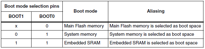
When the BOOT0 pin is 0, It will be booting from System Memory that invokes the on-chip bootloader, which is present in the chip directly from the factory, before you’ve programmed anything into the on-chip flash. This allows you to load (program) code into the device from an external interface such as UART or USB. This is explained in detail in the manual.
When the BOOT1 pin is 1 and the BOOT0 pin is 1, the Main flash memory is where your code typically goes. In normal operation, your code will reside in flash, and on Power On Reset (POR), the CPU will fetch the reset vector and initial stack pointer (SP) from flash. You can load flash via JTAG, the on-chip bootloader (above), etc. You can read this post which explains what will happen when we press the reset button (Reset sequence).
|
|
|
Lastly, when the BOOT1 pin is 1 and the BOOT0 pin is 1, we can load code into RAM (JTAG, runtime) and then boot/run from there. This isn’t often used, usually, you’re doing something tricky like a temporary bootloader or the like.
If you are going to flash the binary file using the system bootloader and STM32CubeProgrammer through UART, then you have to make the BOOT1 pin to 0 and BOOT0 pin to 1. If you are going to use the STLink Programmer, then do not worry about these pins. Keep these pins to 0.
Simple STM32F103 Bootloader – Introduction
In this tutorial, we are going to write a simple STM32f103 bootloader that calls the application.
What we are going to implement in this tutorial?
In this tutorial, I am going to create two projects. One is for the bootloader and the other is for the Application. Both projects will create different binary files. We are going to place these binary files in our Flash memory.
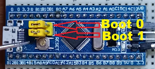
If you see the above image, our total flash memory is 64Kb. In that, we are going to place the bootloader into 0x08000000 (16Kb). Then next 1Kb for reserved(future use). Finally, we are going to place the application from 0x08004400 (47Kb). If you are using a 128KB flash variant, then you can use 111Kb for the application.
|
|
|
So, now what will happen when you press the RESET button? It reads the BOOT pins and both are 0, then it starts from the flash memory. We have placed the bootloader in the starting position. So, it will read the stack address from 0x08000000 and store that in the MSP register. Then it takes the reset handler address from 0x08000004 and jumps to that.
Then it does the all memory initialization of data segments and it calls the bootloader’s main function. In the bootloader’s main function, we will do some other operations. In this example, I am not going to do anything except ON/OFF the green LED. Once after that, we have to call the application.
This is what we are going to implement in this tutorial. If you don’t understand it properly, then I would recommend you to see the video explanation. You will understand.
Simple STM32F103 Bootloader
Create the project
For this demonstration, I will be using the STM32CubeIDE. Frankly speaking, I don’t like this kind of IDEs that automatically generates the code. I like to write everything from scratch. Then only I can able to learn properly. But as this is just a bootloader tutorial, we will let this IDE to generate the code for us to save some time. But if you are implementing the bootloader for your project, then I suggest you to use it without this auto-generated code.
Create the bootloader
Please check the below video to create the project and enable GPIO (PC13 for LED) and UART1 (Debug prints). This will be easy to come along with me.
|
|
|
Once you created the project and enabled the GPIO (PC13) and UART1 (PA9 and PA10), now we will have the auto-generated code. We will start from here.
Like the C program, printf won’t work here. We have to redirect the printf to our debug COM port (UART1). Add the code given below to your project.
Note: Whenever you are adding your code, you must include your code between the USER CODE BEGIN and USER CODE END. If you add your code anywhere else, then it will be removed when you regenerate the code. Keep this in your mind.
/* USER CODE BEGIN Includes */
#include <stdio.h>
#include <string.h>
/* USER CODE END Includes */

/* USER CODE BEGIN 4 */

#ifdef __GNUC__
  /* With GCC, small printf (option LD Linker->Libraries->Small printf
     set to 'Yes') calls __io_putchar() */
int __io_putchar(int ch)
#else
int fputc(int ch, FILE *f)
#endif /* __GNUC__ */
{
  /* Place your implementation of fputc here */
  /* e.g. write a character to the UART3 and Loop until the end of transmission */
  HAL_UART_Transmit(&huart1, (uint8_t *)&ch, 1, HAL_MAX_DELAY);

  return ch;
}
/* USER CODE END 4 */
Now, you can use the printf. That will be redirected to the UART1. So, you watch those prints from the serial terminal.
And I have added the below code in my main.c.
|
|
|
/* USER CODE BEGIN PM */
#define MAJOR 0
#define MINOR 1
/* USER CODE END PM */


/* USER CODE BEGIN PV */
uint8_t BL_Version[2] = { MAJOR, MINOR };
/* USER CODE END PV */


/* USER CODE BEGIN PFP */
static void goto_application( void );
/* USER CODE END PFP */


/* USER CODE BEGIN 4 */

static void goto_application( void )
{
	printf("Gonna Jump to Application...\n");
	void (*app_reset_handler)(void) = (void*)(*((volatile uint32_t*)(0x08004400 + 4U)));

	app_reset_handler();
}

/* USER CODE END 4 */
What did we do in the above code?
In the above code, we have created one variable for the Bootloader version. And, we have created the goto_application function which calls the application reset handler. We have used the function pointer and volatile keyword for this purpose. How do we call the application? We know the vector table address (0x08004400) of the application. In that address, stack memory’s starting address will be present. Then in the ( 0x08004400 + 4) address, the application reset handler’s address will be present. Now we have the application reset handler’s address. Then using the function pointer, we can call the application’s reset handler. Simple right?
I will call this goto_application function from the main function.
Then check the flash address in the linker script called STM32F103C8TX_FLASH.ld file. In the memory definition, make sure you have the below address and the sizes are present. If not, then please modify it.
/* Memories definition */
MEMORY
{
  RAM    (xrw)    : ORIGIN = 0x20000000,   LENGTH = 20K
  FLASH    (rx)    : ORIGIN = 0x8000000,   LENGTH = 16K
}
Now, we are ready with the bootloader. Let’s create the application.
Create the application
Please check the below video to create the project and enable GPIO (PC13) and USART 1
|
|
|
Like bootloader, we will enable the printf by adding this code.
/* USER CODE BEGIN Includes */
#include <stdio.h>
#include <string.h>
/* USER CODE END Includes */

/* USER CODE BEGIN 4 */

#ifdef __GNUC__
  /* With GCC, small printf (option LD Linker->Libraries->Small printf
     set to 'Yes') calls __io_putchar() */
int __io_putchar(int ch)
#else
int fputc(int ch, FILE *f)
#endif /* __GNUC__ */
{
  /* Place your implementation of fputc here */
  /* e.g. write a character to the UART3 and Loop until the end of transmission */
  HAL_UART_Transmit(&huart1, (uint8_t *)&ch, 1, HAL_MAX_DELAY);

  return ch;
}
/* USER CODE END 4 */
Then we will be creating one variable for the application version and simply blink the led in the while loop with a one-second delay.
/* USER CODE BEGIN PM */
#define MAJOR 0
#define MINOR 1
/* USER CODE END PM */

/* USER CODE BEGIN PV */
uint8_t APP_Version[2] = {MAJOR, MINOR};
/* USER CODE END PV */


  /* USER CODE BEGIN 2 */
  printf("Application %d:%d Started!!!\n", APP_Version[0], APP_Version[1]);
  /* USER CODE END 2 */


  /* USER CODE BEGIN WHILE */
  while (1)
  {
    /* USER CODE END WHILE */

    /* USER CODE BEGIN 3 */
	  HAL_GPIO_TogglePin(GPIOC, GPIO_PIN_13);
	  HAL_Delay(1000);							//1sec delay
  }
  /* USER CODE END 3 */
Then, check the linker script in the Application project (STM32F103C8TX_FLASH.ld). As the starting address of the application is 0x08004400 we must set the flash as 0x08004400. And set the size to 47KB. If you are using a 128Kb variant, then set the size to 111Kb. Refer to the code below.
/* Memories definition */
MEMORY
{
  RAM    (xrw)    : ORIGIN = 0x20000000,   LENGTH = 20K
  FLASH    (rx)    : ORIGIN = 0x8004400,   LENGTH = 47K
}
Once you have done this, then we have to tell the controller that the vector table address is changed to 0x08004400. To do that, go to the application source code -> core -> Src -> system_stm32f1xx.c.
Please uncomment the USER_VECT_TAB_ADDRESS macro. Then, set the vector table offset. Right now offset is 0, which means, it is pointing to 0x08000000. We have to change that to 0x08004400. So, just writing 0x04400 is enough. Now, it will point to 0x08004400. Refer to the below code.
|
|
|
#define USER_VECT_TAB_ADDRESS

#if defined(USER_VECT_TAB_ADDRESS)
/*!< Uncomment the following line if you need to relocate your vector Table
     in Sram else user remap will be done in Flash. */
/* #define VECT_TAB_SRAM */
#if defined(VECT_TAB_SRAM)
#define VECT_TAB_BASE_ADDRESS   SRAM_BASE       /*!< Vector Table base address field.
                                                     This value must be a multiple of 0x200. */
#define VECT_TAB_OFFSET         0x00000000U     /*!< Vector Table base offset field.
                                                     This value must be a multiple of 0x200. */
#else
#define VECT_TAB_BASE_ADDRESS   FLASH_BASE      /*!< Vector Table base address field.
                                                     This value must be a multiple of 0x200. */
#define VECT_TAB_OFFSET         0x00004400U     /*!< Vector Table base offset field.
                                                     This value must be a multiple of 0x200. */
#endif /* VECT_TAB_SRAM */
#endif /* USER_VECT_TAB_ADDRESS */
Build the application and bootloader.
I did not provide the full source code in this post. I know that you will get confused by seeing the source code. Please refer to the code that we have posted on GitHub, and refer to the video explanation.
Let’s flash the bootloader to 0x08000000 and application to 0x08004400.
STM32F103 Bootloader Output
Now you will see the Bootloader and Application prints in the serial terminal. When the bootloader is running, you can see that Green LED is blinking very fastly and When the application is running, the Green LED is blinking with a 1-second delay. You can see the demo of this example.
Video Explanation
Please check the below video explanation.
|
|
|
In our next tutorial, we will use the write bootloader to update the application through UART.
You can also read the below tutorials.
Embedded Software | Firmware | Linux Devic Deriver | RTOS
Hi, I am a tech blogger and an Embedded Engineer. I am always eager to learn and explore tech-related concepts. And also, I wanted to share my knowledge with everyone in a more straightforward way with easy practical examples. I strongly believe that learning by doing is more powerful than just learning by reading. I love to do experiments. If you want to help or support me on my journey, consider sharing my articles, or Buy me a Coffee! Thank you for reading my blog! Happy learning!
